


®
Chapter 2 PID settings
20 CNT-APG002-EN
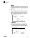
Adjusting error deadband for modulating outputs
In most applications, start with an error deadband of five or ten times the
sensor resolution. For example, thermistors have a resolution of approxi-
mately 0.1°F (0.06°C), so 0.5°F (0.3°C) is an appropriate error deadband.
This error deadband ensures that the sensor reading has changed an ade-
quate amount before the controller responds.
IMPORTANT
The error deadband should not be smaller than the sensor resolution or
the controller will react to noise.
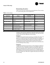
Adjusting error deadband for staged outputs
This section shows how to adjust the error deadband for staging applica-
tions. Refer to “Staging cooling-tower fans” on page 37 for information on
setting other PID properties for staging applications.
Finding the best error deadband for staged output applications is more
difficult than for modulating outputs. Instead of using a continuous actu-
ator, such as a chilled-water valve, staged systems use binary outputs to
start and stop pieces of equipment, such as fans in a cooling tower. Each
piece of equipment contributes a set amount to the final output. When
determining the error deadband for staged outputs, the main goal is to
reduce equipment cycling.
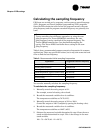
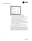
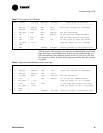
Table 4 on page 19 provides useful initial values, but the error deadband
should be adjusted at the site with the equipment running.
Follow these guidelines when adjusting the error deadband:
• If possible, do not let equipment minimum-on and -off times control
how long a particular stage is used. Using minimum-on and -off times
to perform system control generally results in unpredictable behavior.
The error deadband should be set so that a stage is always on longer
than its minimum-on time.
• Ask how tight control should be. A smaller error deadband results in
tighter control, but control should not be so tight that minimum-on
and -off times affect the stages.
For example, for a variable-air-volume (VAV) air-handler turning on
cooling stages, control can be somewhat loose. The individual VAV
boxes control their valve to the space depending on the supply air
temperature. If the supply air temperature is relatively warm, the
VAV box allows more air flow. If the supply air temperature is some-
what cool, the VAV box constricts the air flow.
• The contribution of each stage can change depending on external cir-
cumstances, so make adjustments under worst case conditions.
Adjust the error deadband for cooling tower fan stages on very warm
days, and adjust the error deadband for boiler stages on very cold
days.