


Other PID settings
CNT-APG002-EN 21
®
With the preceding guidelines in mind, use the following procedure to
determine error deadband.
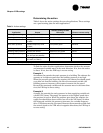
To adjust the error deadband for staged outputs:
1. Run the system manually.
If possible, do so under worst case conditions for the site. Although it
is not always possible for a technician to do this, it is possible for a
well-trained customer.
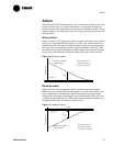
2. Find the smallest change in temperature, ∆T, that the first stage can
contribute (the quantity could also be building static pressure for fans
or flow for pumps).
Pay attention to possible changes in external circumstances, such as
the amount of water flow. If the system uses a lead-lag approach to
the equipment, it will be necessary to find the minimum ∆T for all
stages.
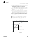
3. Multiply ∆T by 0.45 (the error deadband should be slightly less than
half of ∆T).
Keep in mind the resolution of the sensor. You may need to round the
error deadband to a more reasonable value.
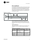
4. Run the system with the new error deadband.
Each stage should be on longer than its minimum-on time and cycling
should be reduced as much as possible.
Other PID settings
Other PID settings not discussed in this chapter include:
• Proportional bias, which takes the place of derivative gain in propor-
tional-only control (see “Proportional calculation” on page 3)
• Minimum and maximum output, which limit the range of output of
the PID loop
• Enabled and disabled modes, which enable the PID output or disable
it to a default value
• Fail-safe mode, which sets the PID output to a default value if the
controller receives a fail flag from the hardware input that provides
the measured variable
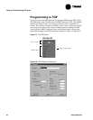
Chapter 3, “Programming PID loops,” shows how to program these set-
tings for Trane controllers.