


Chapter 4: Controller Connections and Operation
Power On 4-7
(Red stripe)
1 2 3 4 5
6 7 8 9
IFT-9512 cable
D
u
a
l
C
O
M
P
o
r
t
1 2 3 4 5
6 7 8 9
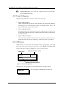
Host Computer
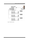
Connect to the RS-232C
port of the host computer
Controller
COM 1 COM 2
IFT-9512 cable
IFT-9011 Null Modem
RS-232 Cable
Customer
Provided
1
1
2
2
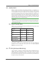
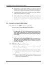
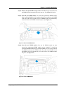
Figure 4-5: RS-232C Connection
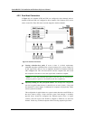
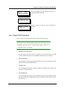
Two SCSI ports on the si x channel mo dels (ES U16U G4010-62-0030 and ES U16UG4010 -65-0030) can be use d for capacit y expansion to cascade a RAID s ystem wit h a JBOD. Conne ct the SCSI ports on t he controlle r box’s f ace plate (mar ked as CH4 and C H5) to por ts on a JBOD . No terminat ion setti ng is necess ary, and ther e is no limi tation as to which expansi on port should be conne cted with whic h port on a J BOD. To be abl e to moni tor the stat us of diffe rent JBOD co mponents it is necessar y to use a JB OD that can be connected to the I
2
C port on the ES U1 6U subsyste m. See Error ! Reference so urce not fo und..
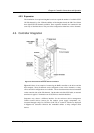
4.5. Power On
Once all the components have been installed in the SR controller, the host channels have
been connected to the host and the drive channels have been connected to the SCSI-320
drives, the controller can be powered on.
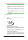
4.5.1 Check List
BEFORE powering on the SR controller, please check the following:
Memory module: Make sure that a memory module has been correctly installed
on the controller board.
BBU modules: If installed, make sure the BBU charger board and the BBU
battery pack have been installed correctly.
Host computers: Host I/O channels have been connected to the host computers
Hard drives: Hard drives have been connected to the drive I/O channels.
Power module connection: The PSU connectors at the back of the controller
board have been connected to an appropriate PSU.