


SentinelRAID 170 Installation and Hardware Reference Manual
4-6 Other Connections
NOTE:
It is recommended to use the embedded terminators on host or drive channels by
setting DIP switches, and then installing an external terminator on the other end of
your SCSI cable. If a drive fails, data traffic will remain unaffected. Please note of the
following:
1. Refer to the installation documents that came with your drives for information on
jumper settings.
2. Set a unique SCSI ID address on each drive. Avoid ID 7 – this is a default
reservation for the controller. In redundant controller mode, each of the two
controllers takes an ID on each SCSI bus. The combination can be ID 6 and ID 7
or ID 8 and ID 9.
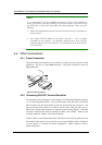
4.4. Other Connections
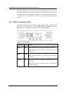
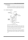
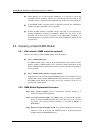
4.4.1 Power Connection
The power input and connection of the controller is exactly the same as those for hard
disk drives. Be sure to connect both connectors. The power connection is shown in
Figure 4-4 below.
Figure 4-4: PSU Connection
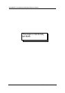
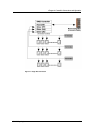
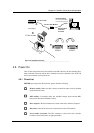
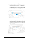
4.4.2 Connecting RS-232C Terminal Emulation
The controller can be configured via a PC running a VT-100 terminal emulation program
or a VT-100-compatible terminal. The provided combo cable (IFT-9512) converts the
RS-232 signals from the 20-pin header into the two 9-pin D-Sub male connectors. The
pin layout of the 9-pin connectors is similar to that of a PC’s serial port and is set as a
DTE device. Proper cable connection is displayed in the following diagram. The DB-9
connectors of the IFT-9512 cable are marked as “COM 1” and “COM 2.” Please use the
connector marked as “COM 1” for terminal emulation.
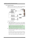
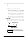
Connect COM 1 to the included null modem (IFT-9011) and connect the other end of the
null modem to the outside of your enclosure or to an external RS-232 cable. COM ports
can also connect to a modem for remote configuration. COM 2 cannot be used to
download firmware.