


Chapter 3: Controller Monitoring
Controller Monitoring Overview 3-1
Chapter 3
Controller Monitoring
3.1. Controller Monitoring Overview
The SR controller is equipped with a variety of self-monitoring features that help keep
controller managers informed of the controller’s operational status. These monitoring
features provide vital feedback that helps you maintain the operational integrity of your
controller. Prompt response to warnings and failure notifications will improve the overall
operation and help ensure the longevity of the SR controller.
Self-monitoring features include:
♦ Management firmware (FW): The SR controller comes with pre-installed FW
(version 3.31 or above). Device status information can be obtained from the FW.
This FW can be accessed using either the LCD panel or a PC hyper-terminal. The
FW is fully described in the Generic User's Manual that came with the subsystem.
Please refer to this manual for further details.
♦ RAIDWatch: RAIDWatch is a fully integrated Java-based Graphics User Interface
(GUI) that came with the controller and can be used to monitor the controller
remotely. You can use the powerful Notification Process Center (NPC) sub-
module to keep you informed over a variety of communication devices such as fax,
pager, e-mail, etc. The installation and operation of RAIDWatch is fully described
in the RAIDWatch User’s Manual. Please refer to this manual for further details.
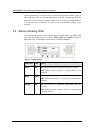
♦ LEDs: Device status indicating LEDs are placed on the front panel of the SR
controller. These LEDs inform you of the integrity and status of different controller
items. You should become familiar with these LEDs and be aware of their
functions.
♦ Audible alarm: An audible alarm is present on the controller board and will be
triggered if any of a number of threatening events occur. These events usually
jeopardize the functional and operational integrity of the controller board and must
be heeded at all times. Events such as a breach of the temperature threshold will
trigger the alarm and if an onsite controller manager is present, the manager should
use either the LCD panel or the PC hyper-terminal to determine the cause of the
alarm and take the appropriate corrective measures.
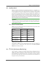
♦ I
2
C: The I
2
C bus monitors the operational integrity of a variety of components.