


SentinelRAID 170 Installation and Hardware Reference Manual
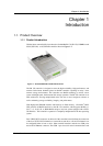
1-2 Product Overview
connects to a PC hyper-terminal that is used to configure the controller and the subsystem
in which it is embedded. The LAN port enables the controller to connect to the web-
based RAIDWatch™ management program that enables you to manage your controller
from anywhere in the world. Two power supply unit (PSU) connectors ensure the
controller can be connected to dual-redundant power supplies.
An LCD panel is conveniently attached to the front of the controller box and can also be
used for controller configuration and troubleshooting. The LCD panel has three
navigation buttons and three status-indicating LEDs.
1.1.2 Enclosure
The SR controller enclosure is divided into a front and rear section.
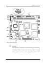
1.1.2.1 Controller Box
The controller box contains both the controller board and the separately purchased,
independently installed DIMM modules. Two optional items, the daughter board and the
battery backup unit (BBU) module, are also installed in the controller box. To access the
controller board it is necessary to remove the top cover of the controller box. The top
cover is secured to the controller box with four retention screws, two on each side.
WARNING:
Although the controller board can be accessed by removing the enclosure top cover, it
should always be remembered that the controller board is a very sensitive component
and can be easily damaged. When accessing the controller board it is imperative that
all safety precautions stipulated in Chapter 2 are strictly adhered to.
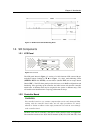
1.1.2.2 Front Side
The LCD panel located on the front panel is used to configure and manage the controller
and storage devices to which it is attached. It is connected to the controller board with a
ribbon cable.
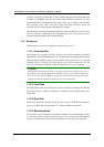
1.1.2.3 Rear Side
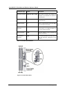
The rear side of the SR controller chassis provides access to the SCSI-320 connectors,
power cord sockets, RS-232C serial port, I
2
C connector and battery connector.
1.1.2.4 Mounting Holes
The controller can be installed into an industrial standard 5.25-inch half-height canister.
To secure the controller within an enclosure chassis, screws must be inserted through the
enclosure’s mounting rails, into the four mounting holes on the sides of the controller.