


Chapter 1: Introduction
SR Components 1-3
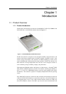
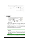
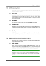
Figure 1-2: SR Enclosure Canister Mounting Holes
1.2. SR Components
1.2.1 LCD Panel
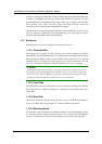
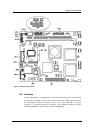
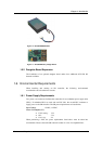
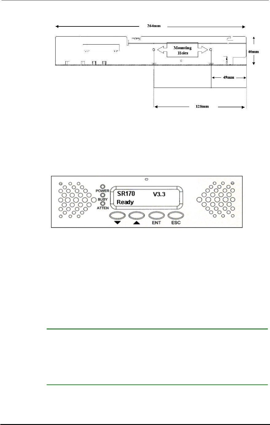
Figure 1-3: LCD Panel
The LCD panel shown in Figure 1-3 consists of a 16x2 character LCD screen with two
navigation buttons (labeled as W V in Figure 1-3), three status-indicating LEDs
(POWER, BUSY and ATTEN), an enter button (labeled ENT) and an escape button
(labeled ESC). The LCD front panel provides full access to all RAID configurations and
monitoring. After powering up the controller, the initial screen will show the controller
model name. A different name may be assigned for the system or different arrays. This
will enable easier identification in a topology with numerous arrays.
1.2.2 Controller Board
WARNING:
The controller board is a very sensitive component that can be easily damaged. When
working with the controller board make sure all safety precautions are strictly
adhered to. Failure to adhere to these safety instructions can result in severe damage
to the controller board.
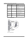
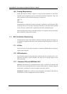
The heart of the SR 170 controller is the SCSI-to-SCSI controller board (see Figure1-4).
The controller board has four SCSI-320 I/O channels (CH0, CH1, CH2 and CH3). Two