


SentinelRAID 170 Installation and Hardware Reference Manual
1-4 SR Components
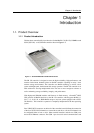
upgrade sockets allow for the installation of a daughter board that facilitates the addition
of four SCSI-320 I/O channels. All I/O channels (both base channels and expansion
channels) can be configured as either host or drive channels.
The controller board also comes with a 68-pin SDRAM DIMM socket that facilitates the
installation of a 64MB to 1GB SDRAM DIMM module. A variety of other onboard
connectors and jumpers facilitate the connection of a variety of accessory components
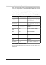
like battery module charger boards. These jumpers and connectors are listed in Table 1-1.
Connector Type Label Description
Daughter Board
Connectors
JP1 and JP13 These two connectors are used if an
expansion daughter board is being installed
on the controller module.
Battery Charger
Board Connector
JP6 and JP11 These connectors are used to mount the
optional battery charger board onto the
controller board.
LED Connectors JP2, JP3, and JP4 Partner Failed! (JP2), Not Ready (JP3) and
Ready (JP4)
Not Mask Interrupted
(NMI)
JP5 Only used by Infortrend for debugging.
Reset JP7 Used to reset the controller
LCD Type Selection JP10 Only used by Infortrend for testing.
LCD Connector JP14
This jumper is used to connect the LCD
screen to the controller board with a ribbon
cable.
Restore Firmware
Default
JP19 This jumper is used to restore the firmware
default settings.
Front Panel Fan
Status Detect
JP22 Helps to determine the operational status of
the fans at the back of the front panel.
Table 1-1: Controller Jumpers and Connectors
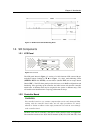
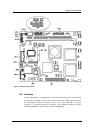
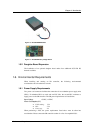
The jumpers listed in Table 1-1 above are all located at the front of the controller board.
(See Figure1-4)