


SentinelRAID 170 Installation and Hardware Reference Manual
2-4 Accessing the Controller Board
2.6. Accessing the Controller Board
2.6.1 Overview
WARNING:
The controller board is a very sensitive component and must therefore be handled with
extreme care. Before accessing the controller board, please ensure that all anti-static
precautions previously stipulated are strictly adhered to.
The controller board is located in the controller box and should only be removed from the
controller box if the controller board fails. However, it is necessary to access the
controller board in order to install the DIMM module, optional BBU module and the
optional daughter board. To access the controller board, remove the top cover of the
controller box. Replace the cover after the different components have been correctly
installed.
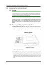
2.6.2 Removing and Replacing the Chassis Top Cover
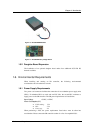
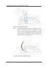
♦ Removing the top cover: The chassis top cover is secured to the chassis with four
retention screws (two on each side). To remove the top cover, remove these four
retention screws (see Figure 2-1). Once they have been removed, gently lift the top
cover up to expose the controller board.
Figure 2-1: Remove the top cover
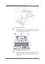
♦ Replacing the top cover: After the controller board components have been installed,
the chassis top cover must be replaced. To do this, make sure the front panel LCD
screen is properly positioned. Next, ensure the top cover is correctly oriented. Notice
that the two rectangular holes in the top cover are located at the front and must be
installed in this way. Once correctly oriented, gently place the top cover on the
chassis and re-insert the four previously removed retention screws (two on each
side).