


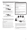

33
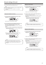
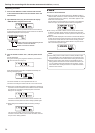
3. Turn the F2 dial to select “Yes”, and then press the F2
dial.
Auto IP setting starts.
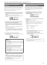
During auto IP setting, the progress is indicated by the number of
“
” which are reduced one by one.
1.AUTO SET
When all the operations have been completed successfully, the
following message appears.
1.AUTO SET
COMPLETE
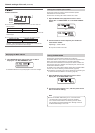
The remote cameras and the switcher are automatically rebooted,
and they restart with the new IP addresses which were set.
The remote cameras can now be operated from the unit.
The function for linking the switcher with the unit can now be used.
When setting the IP addresses failed, the following message
appears.
1.AUTO SET
SET UP ERR!
The cause of the problem is likely to be a network malfunction.
Check the connection status of the hub and LAN cables, and then
retry the auto IP setting operation.
Leaving the IP addresses of the additional devices to
be introduced unchanged and automatically updating
the connection destination IP addresses set on the
unit
<Overview of operation>
The link settings can be configured by executing “KEEP IP ADR” in
AUTO IP menu [37].
With “KEEP IP ADR”, the unit first searches within the same subnet
mask.
Then, links are set between the newly detected remote cameras and
camera numbers for which the connection type is set to “NoAsign” on
the unit.
At that time, the IP addresses of the remote cameras are kept as is
and the connection destination IP address values set on the unit are
overwritten.
Likewise, when a new switcher is detected while the connection type for
the switcher is set to “NoAsign” on the unit, the link setting is configured
by keeping the IP address of the detected switcher and overwriting the
connection destination IP address value set on the unit.
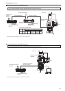
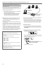
Example:
(1) Operation is being performed with the three remote cameras A, B
and C set to CAM1, CAM2 and CAM3, respectively.
(2) The new remote camera D (with the following IP address value)
is added.
Remote camera D : 192.168.000.020
(3) Connection types set on the unit (CTRL TYPE menu [36])
CAM1 : Network
CAM2 : Network
CAM3 : Network
CAM4 : NoAsign
(4) Connection destination IP address set on the unit (MANUAL IP
menu [39])
CAM4 : 192.168.000.013
When “KEEP IP ADR” is executed in this state, the IP address of
remote camera D is not changed, the connection destination IP
address set on the unit is overwritten with the following value, and a
link is set to remote camera D.
Connection destination IP address of CAM4:
192.168.000.200
192.168.000.013
192.168.000.200
192.168.000.200
Remote
camera A
Remote
camera B
Remote
camera C
CAM4
Remote
camera D
Connection destination IP
address of CAM4
If camera numbers for which the connection type is set to other than
“Serial” include a camera number for which the connection destination
IP address is set to the same value as the IP address of a detected
remote camera, the connection destination IP address set on the unit
is not updated. The connection destination IP address is kept as is
and a link is set for the corresponding camera number and remote
camera.
Set the subnet mask of the unit and remote camera to the same
value. If the subnet masks are different, no operations using the
network will be possible.
Note
Settings for connecting with the remote cameras and switcher (continued)