


30
Settings for connecting with the remote cameras and switcher (continued)
Setting the connection types for remote
cameras (serial/IP/no connection)
1. Set the connection types for camera numbers CAM1 to
CAM100.
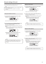
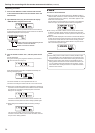
Open CTRL TYPE menu [36] and turn the F1 dial to display the
camera number to set.
1.CAM1
NoAsign
2. Turn the F2 dial to select the connection type, and then
press the F2 dial to confirm the setting.
Serial : Serial connection
Network : IP connection
NoAsign : No connection (default setting)
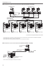
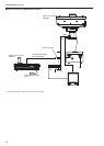
The TO PAN/TILT HEAD connectors [1] to [5] for serial
connections correspond to each of the camera numbers CAM1
to CAM5.
The serial connection “Serial” setting cannot be selected for
CAM6 to CAM100.
When performing the steps described in “auto IP setting”
(page 30), set the target camera number to “NoAsign”.
Note
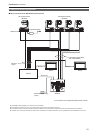
Setting the connection type (IP/
no connection) for the switcher
1. Set the connection type for the switcher to be linked
with the unit.
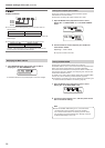
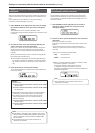
Open SW SETUP menu [41] and turn the F1 dial to open the
“1. SW CTL” item.
1.SW CTL
NoAsign
2. Turn the F2 dial to select the connection type, and then
press the F2 dial to confirm the setting.
Network : IP connection
NoAsign : No connection (default setting)
When performing the steps described in “auto IP setting”
(page 30), set the “1. SW CTL” item to “NoAsign”.
Note
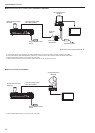
Setting the IP addresses automatically
(auto IP setting)
When auto IP setting is executed, the settings for linking between the
remote cameras and switcher connected within the same subnet as the
unit are configured automatically.
The following explanations are split into configuring the settings for the
first time (when the remote cameras and switcher are in the factory
default state) and introducing additional remote cameras or a switcher
into an environment in which IP connections are already in use.
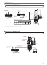
When configuring the settings for the first time
<Overview of operation>
The link settings can be configured by executing “RENEW IP ADR” in
AUTO IP menu [37].
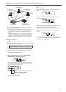
With “RENEW IP ADR”, the unit first searches within the same subnet
mask. Then, a link is set between each detected remote camera and
a camera number for which the connection type is set to “NoAsign”
on the unit.
At that time, the IP address of each remote camera is overwritten with
the connection destination IP address value set for the corresponding
camera number on the unit.
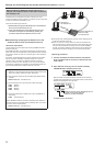
Likewise, when a new switcher is detected while the connection
type for the switcher is set to “NoAsign” on the unit, the link setting is
configured by overwriting the IP address of the detected switcher with
the connection destination IP address value set on the unit.
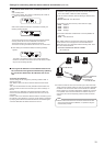
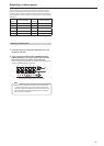
Example:
(1) IP addresses set for remote cameras A, B and C.
Remote camera A : 192.168.000.010
Remote camera B : 192.168.000.010
Remote camera C : 192.168.000.010
(2) Connection types set on the unit (CTRL TYPE menu [36])
CAM1 : NoAsign
CAM2 : NoAsign
CAM3 : NoAsign
(3) Connection destination IP addresses set on the unit (MANUAL
IP menu [39])
CAM1 : 192.168.000.010
CAM2 : 192.168.000.011
CAM3 : 192.168.000.012
When “RENEW IP ADR” is executed in this state, the IP
addresses of remote cameras A to C are overwritten with the
following values, and a link is set to each of the camera numbers
CAM1 to CAM3, respectively.
Remote camera A : 192.168.000.010
Remote camera B : 192.168.000.011
Remote camera C : 192.168.000.012