13
5
F1 dial [F1]
F2 dial [F2]
Use these to operate the menus of the unit or the OSD menu of a
remote camera.
Use the CAMERA OSD button (4) to select which operation to
perform.
When the dials are used to operate the menus of the unit, the F1 dial
operates the items displayed at the top of the LCD panel of the unit,
and the F2 dial operates the items displayed at the bottom of the LCD
panel.
Operation of the OSD menu of a remote camera differs depending on
the camera type.
⇒ “Operating the OSD menu of a remote camera” in Operations and
Settings (page 12)
6
EXIT button [EXIT]
Use this to cancel the changes to the settings during operation of the
OSD menu of a remote camera.
It cannot be used during operation of the menus of the unit.
⇒ “Operating the OSD menu of a remote camera” in Operations and
Settings (page 12)
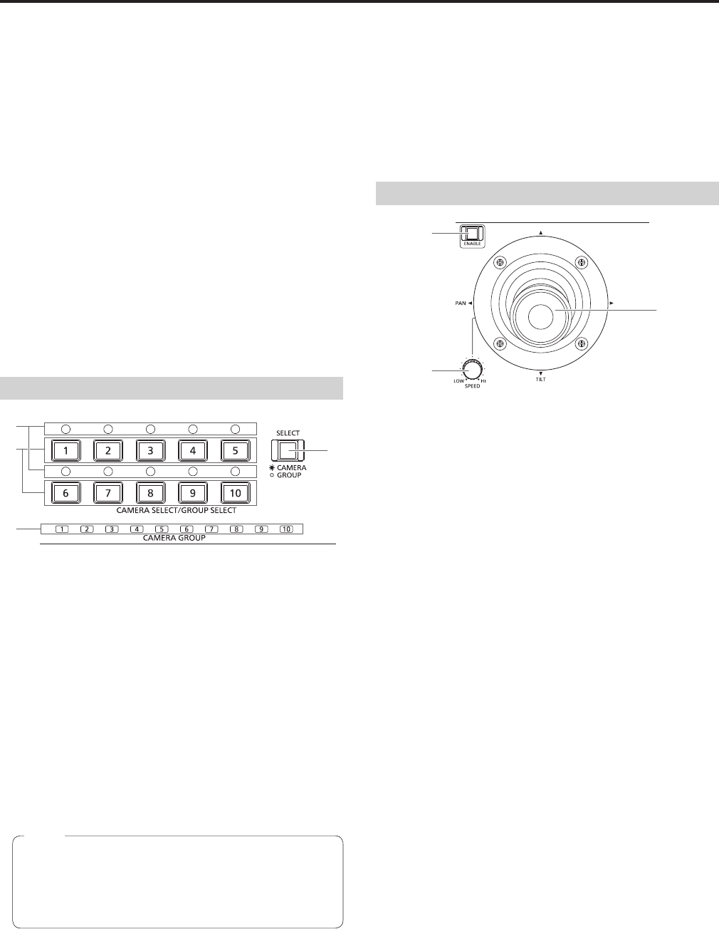
Camera selection section
7
Mode selection button [SELECT]
Each press of this switches the button indicator between on and off
in the order of on → off → on, and so on, and switches the operation
mode of the camera selection buttons (8).
Button indicator on : Camera selection mode
Button indicator off: Camera group selection mode
8
Camera selection buttons
[CAMERA SELECT/GROUP SELECT 1 to 10]
Use these to select the remote camera or camera group to control
from the unit.
Pressing any of [1] to [10] in camera selection mode switches to the
corresponding remote camera.
Pressing any of [1] to [10] in camera group selection mode switches
to the corresponding camera group and turns on the corresponding
camera group indicator (9).
If a camera selection button is pressed to switch the remote
camera that the unit controls while the OSD menu of a remote
camera is displayed, the CAMERA OSD button indicator (4)
turns off and the OSD menu of the remote camera originally
selected disappears.
Note
9
Camera group indicators [CAMERA GROUP 1 to 10]
The indicator for the selected camera group number is on.
:
Camera status indicators [1] to [10]
These indicate the statuses of the remote cameras assigned to [1] to
[10].
⇒ “Selecting a remote camera” (page 38)
Pan and tilt section
PAN/TILT lever
Use this to control the direction in which the currently selected remote
camera points.
The movement speed differs depending on the angle to which the
PAN/TILT lever is moved.
Moved left or right: The camera points to the left or right.
Moved toward you or away from you:
The camera points up or down.
When the function for linking with a switcher is enabled, you can
use the PAN/TILT lever to control switcher parameters.
⇒ “Setting linking with a switcher” in Operations and Settings
(page 31)
Setting [REVERSE] in PAN DIRECTION menu [26] and TILT
DIRECTION menu [27] changes the direction the camera moves in
relation to the direction that the lever is moved.
<
PAN/TILT SPEED dial [SPEED]
Use this to adjust the operation speed variation amount for PAN/TILT
lever operation.
Turned clockwise : Operation is at a higher speed (HI)
Turned counterclockwise : Operation is at a lower speed (LOW)
=
PAN/TILT ENABLE button [ENABLE]
Use this to enable PAN/TILT lever operation.
Button indicator on or blinking: PAN/TILT lever operation is
enabled.
Button indicator off : PAN/TILT lever operation is
disabled.
The PAN/TILT ENABLE button indicator is on while the PAN/TILT
lever is being used to control the direction in which the remote
camera points.
The PAN/TILT ENABLE button indicator is blinking while the PAN/
TILT lever is being used to control the switcher parameters.
When the [7. P/T/Z CONTROL] item in SW FUNCTION menu [42]
is set to [Button Select], pressing the PAN/TILT ENABLE button
switches the control application of the PAN/TILT lever.
⇒ “Setting linking with a switcher” in Operations and Settings
(page 31)
Parts and their functions (continued)


