


Clarity User Guide, March 1, 2011 - Rev. 1.06
Page 5
Chapter 1 – Getting Started
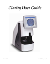
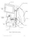
The Clarity Automated Lens Analyzer/Blocker is designed to verify all prescription
parameters including sphere power, cylinder power, axis, optical center location, prism, and
all add powers as well as thickness and front curve information. It will also affix a finish
block to the lens on axis at the geometric center of the frame shape. It is shipped in an almost
ready-to-run condition. This guide will allow you to put the Clarity into service quickly. We
will cover the following topics:
• Unpacking the Clarity
• Applying power and turning on the unit
• Connecting the unit to your lab’s computer system
• Using the touch-panel display and examining some of the operator screens
• Operation including lens insertion and blocking
• Calibration
• Advanced screen functions
The Clarity has many features and settings to allow you to optimize it for your specific lab
environment. It also has diagnostic capabilities and adjustments to fine tune its operation.
This guide does not describe all of the features or adjustments. Once you have become
familiar with operation as described in this guide and want more information, call Technical
Support.
Unpacking the Clarity
The Clarity is shipped in molded foam blocks within a cardboard carton. These blocks need to
be removed prior to removing the machine from the carton. An accessory kit is shipped in
two small cardboard inserts. The shipping carton and shipping materials should be retained in
the event that the unit must be shipped again.
Before removing the Clarity from the packing box and setting it up, please read this guide and
familiarize yourself with the accessories, features and terms used throughout the guide. There
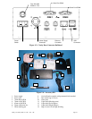
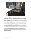
is a glossary of terms in the back of this guide. Once the carton is opened, remove the two
inserts containing the power supply, power cord, and accessory kit. Remove the two side
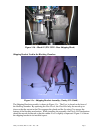
panels and lift the unit out of the carton. Be careful to use the appropriate lift points. (See
Fig. 1.2) Place the unit in the desired location, but out of direct sunlight.
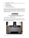
Inspect the contents to ensure you have all the items listed below. (See Fig. 1.4). There
should be 14 items in the two inserts. They are:
1. Power supply
2. Power cord
3. 70mm Plano CR39
4. 70mm -6.00 CR39
5. 65mm +6.00 CR39
6. 58mm calibration disc
7. White marking pen for progressives
8. Oval calibration template with permanent block attached