


includes sixteen Activity LEDs, and the CMS-8 includes eight Activity LEDs.
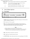
2.2. Back Panel
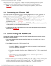
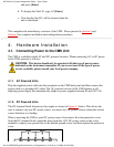
Figure 2.2: Instrument Back Panel
Network Port: An RJ45 Ethernet port for connection to your TCP/IP network. To
communicate via network, you must first specify the IP Address, Subnet Mask, and
Gateway Address as described in Section 5.5.4.
1.
Power Cable Receptacle2.
Power Switch3.
RS232 PORTS: For connection to console ports on target devices. Standard DB9
connectors configured as DTE ports. The RS232 ports are similar to a serial port on a PC.
When connecting a modem, use a standard serial cable. When connecting a PC or other
DTE device use a null modem cable.
Ports 1 and 2 are System Setup Ports, which are used for communication during
set-up and configuration. Note that Supervisor Level command access cannot be
disabled at these ports.
●
Ports 1 and 2 can either be connected to a PC or modem. Connection to a modem
allows control by a remote PC.
●
4.
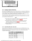
Option Switches: A bank of eight DIP switches, which are used to set the default baud
rate, handshake, message type, and duplex mode. Option Switch functions are described in
Section 4.2.
5.
3. Getting Started
This section provides a brief overview of basic CMS capabilities, and describes simple tests that
WTI CMS-16; Console Management Switch -- User's Guide
file:///C|/WEBPAGE/guides/cms/html/rev_b/Cmsguide.htm (8 of 59) [11/15/2000 10:52:02 AM]