


and press [Enter].
To display the Site I.D., type /J [Enter].b.
Note that the Site I.D. will be cleared when the
unit is initialized.
c.
This completes the introductory overview of the CMS. Please proceed to Section 4 and
Section 5 for complete installation and configuration procedures.
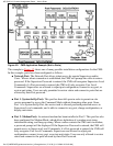
4. Hardware Installation
4.1. Connecting Power to the CMS Unit
The CMS is available in both AC and DC powered versions. When connecting AC or DC power
to the CMS, proceed as follows:
CAUTION: This device should only be operated with the type of power source
indicated on the instrument nameplate. If you are not sure of the type of power
service available, please consult your local power company.
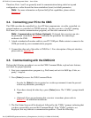
4.1.1. AC Powered Units
Plug the supplied power cable into the receptacle on the CMS back panel and then connect the
power cable to a grounded AC outlet. The AC powered version of the CMS features a self
adjusting power supply that automatically adapts to power supplies between 90 and 250 VAC.
4.1.2. DC Powered Units
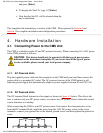
The DC terminal block features two bus inputs as shown in Figure 4.1 below. This allows the
user to connect only one DC power source, or connect two DC power sources where the second
source functions as a backup.
When connecting the CMS to your DC power source, first remove the clear protective cover
from the DC terminal block, attach the wires from the -48V DC power source to the screw
terminals, connect your ground line to the labeled ground screw, and then replace the protective
cover.
WTI CMS-16; Console Management Switch -- User's Guide
file:///C|/WEBPAGE/guides/cms/html/rev_b/Cmsguide.htm (13 of 59) [11/15/2000 10:52:02 AM]