


6-2SectionSpecifications and Nomenclature
85
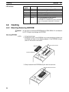
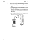
• Before touching the EEPROM or the CPM1-EMU01-V1, first touch a grounded
metallic object to discharge any static build-up. Not doing so may result in mal-
function or damage.
6-2 Specifications and Nomenclature
6-2-1 Specifications
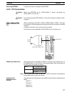
Item Specifications
Supported PCs CPM1, CPM1A, CPM2A, CPM2C, SRM1 (-V2),
CQM1, CQM1H
Read/Write memory areas User program: 15.2 Kwords max.
Data memory: DM 6144 to DM 6655
(Read-only DM and PC Setup)
Expansion instructions: 18 instructions
Connector Connector compatible with CPM1, CPM1A, CPM2A,
SRM1 (-V2), and CQM1 PCs.
For CPM2C and CQM1H PCs, connect via
CS1W-CN114 or CPM2C-CN111 Connecting Cable.
Communications setting 1 start bit, 7 data bits, even parity, 2 stop bits,
9,600 bps
EEPROM (See note 1.) 256-Kbit EEPROM
ATMEL: AT28C256
OMRON: EEROM-JD
Current consumption 129 mA max.
Dimensions Main body (not including cables or connectors):
57 × 92 × 38 mm (W × H × D)
Weight 200 g max. (not including EEPROM)
Note 1. The EEPROM must be purchased separately.
2. For general specifications, refer to the relevant PC manual.
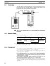
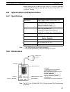
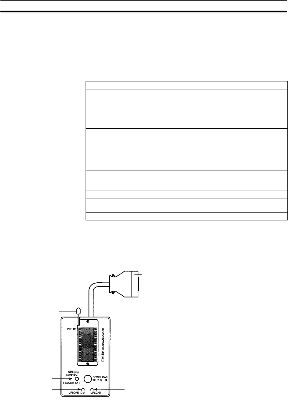
6-2-2 Nomenclature
Lock Lever
For mounting and removing EEPROM.
DOWNLOAD TO PLC Button
Writes all EEPROM data (ladder programs,
data memory etc.) to the PC.
UPLOAD + DM Button
Reads PC user program and contents of
DM 6144 to DM 6655 to EEPROM.
UPLOAD Button
Reads only PC user program to EEPROM.
Lock Lever
Indicator
UPLOAD + DM Button
EEPROM Socket
DOWNLOAD to PLC Button
UPLOAD Button
Peripheral Port
Connector
Note The “PLC” in the “DOWNLOAD TO PLC” Button indicates PCs (Programmable
Controllers).