


3-4SectionWiring and Connections
24
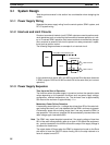
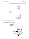
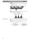
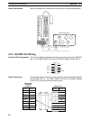
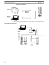
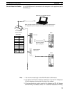
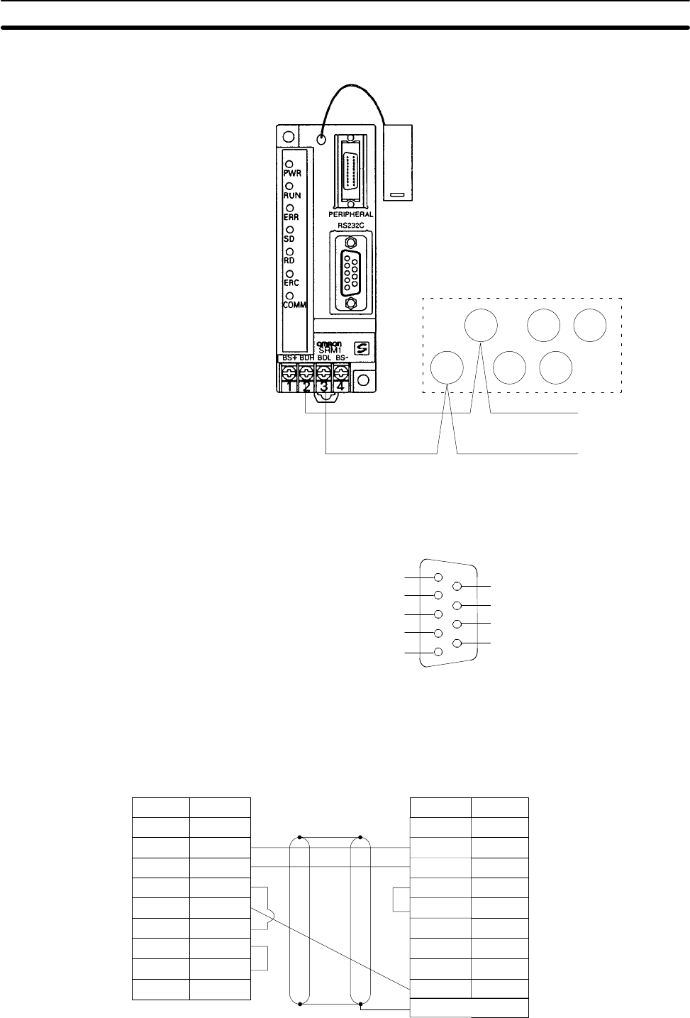
Wiring Connections Wire the CompoBus/S transmission lines as shown in the following diagram.
BD
L
BD
H
BD H
BD L
Slave terminal block
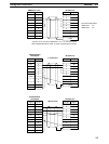
3-4-4 RS-232C Port Wiring
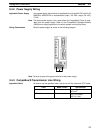
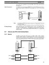
Connector Pin Arrangement The following diagram shows the connector pin arrangement for the RS-232C
port, i.e., the SRM1 (SRM1-C02-V2) and RS-232C Adapter (CPM1-CIF01).
1
2
3
4
5
6
7
8
9
SD
RD
RS
CS
SG
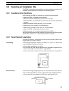
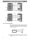
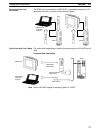
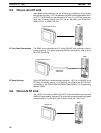
Cable Connections The following diagrams show the communications cable connections between
the RS-232C port, i.e., the SRM1 (SRM1-C02-V2) and RS-232C Adapter
(CPM1-CIF01), and the various external devices.
1
2
3
4
5
6
CD
RD
SD
ER
SG
DR
RS
CS
CI
7
8
9
1
2
3
4
5
6
7
8
9
–
SD
RD
RS
CS
–
–
SG9
RS-232C Port
Pin No.Signal
–
Pin No. Signal
IBM PC/AT or
Compatible
Computer
Hood