


3-1SectionSystem Design
18
3-1 System Design
Take the points covered in this section into consideration when designing the
system.
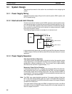
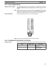
3-1-1 Power Supply Wiring
Separate the power supply wiring from the control system, SRM1 system, and
DC I/O system wiring.
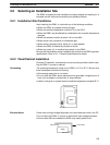
3-1-2 Interlock and Limit Circuits
Construct an external interlock circuit if SRM1 outputs are used to perform recip-
rocal operations such as controlling the forward and reverse operation of a mo-
tor or if incorrect SRM1 operation could cause accidents or mechanical damage.
Also, construct an external limit circuit to prevent run-away movement in opera-
tions such as position control.
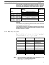
The following diagram shows an example of an interlock circuit.
Interlock Circuit
Motor forward
Motor reverse
MC1
01005
MC2
MC2
01006
MC1
Slave
SRM1
CompoBus/S transmission path
In the interlock circuit above, MC1 and MC2 cannot be ON at the same time even
if SRM1 outputs 01005 and 01006 are both ON at the same time (an incorrect
operation).
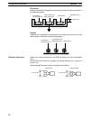
3-1-3 Power Supply Sequence
Time Up to the Start of Operation
The time from when the power supply is turned on to when the operation starts
varies depending on the operation conditions such as power supply voltage,
configuration, ambient temperature, etc. The minimum time is approximately
500 ms and the maximum is approximately 1.1 s.
Momentary Power Failure Detection
A momentary power failure (i.e., a voltage drop to less than 85% of the rated volt-
age) lasting less than 2 ms is not detected and the SRM1 continues to operate.
A momentary power failure lasting longer than 2 ms may cause the SRM1 to
stop operation. If this occurs, operation will be automatically resumed when the
rated voltage again rises above 85%.
Note The SRM1 may repeat stop/start operations if the supply voltage of less than
85% of the rated value gradually goes up or down. If this affects the equipment,
etc., provide a protection circuit which shuts off the output if the supply voltage is
not above the rated value.
The output status of Slaves when the SRM1 is stopped can be set on the Slave
side either to have the ON/OFF status directly prior to the stop retained or to
have all outputs turned OFF.