


2-2SectionUnit Components
15
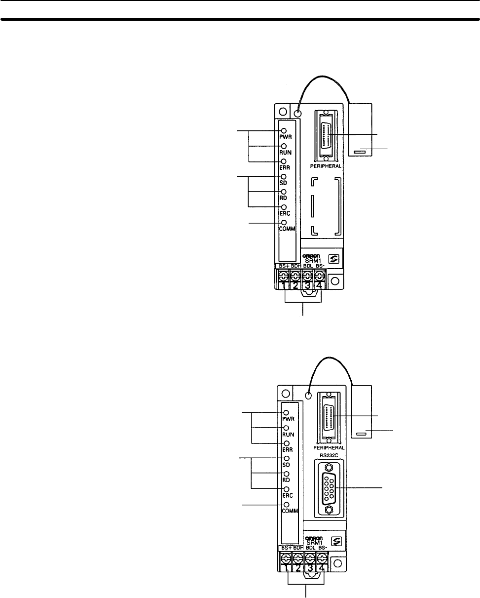
2-2 Unit Components
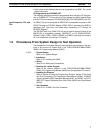
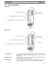
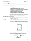
SRM1-C01-V2
1. Terminal block
2. Peripheral port
4. CPU Unit status indicators
5. CompoBus/S communications status indicators
6. Peripheral/RS-232C port communications status indicators
Connector cover
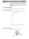
SRM1-C02-V2
1. Terminal block
2. Peripheral port
4. CPU Unit status indicators
5. CompoBus/S communications status indicators
6. Peripheral/RS-232C Port communications status indicators
3. RS-232C Port
Connector cover
1) Terminal Block These terminals connect the power supply (24 V) and the CompoBus/S trans-
mission path. For details regarding power supply wiring, refer to 3-4-2 Power
Supply Wiring.
2) Peripheral Port The Peripheral Port connects the programming tool or an RS-232C or RS-422
adapter. Be sure to use the correct cable.
3) RS-232C Port The RS-232C Port connects to an RS-232C interface such as a personal com-
puter or an OMRON PT. For details, refer to 3-4-4 RS-232C Port Wiring.