


5-1SectionStartup Procedure
60
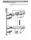
5-1 Startup Procedure
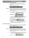
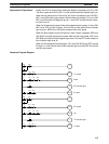
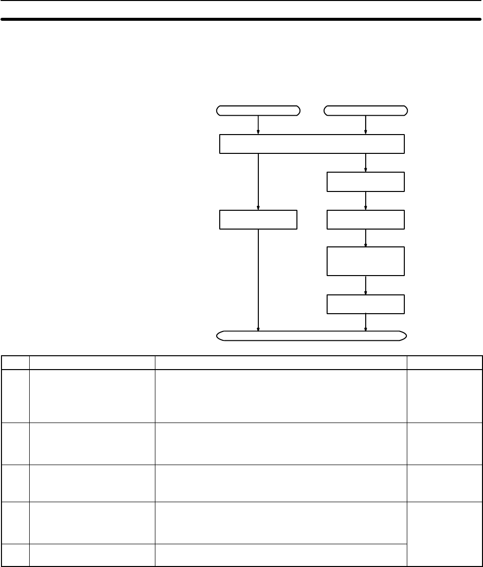
5-1-1 Flowchart for Configuring and Checking the System
Check the following items when configuring the system.
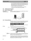
SRM1
CompoBus/S transmission line wiring
Slave Unit
Power supply
connection
Node number
setting
SRM1 startup
I/O device
connections
End
CompoBus/S
communications
mode setting
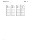
No. Items to check Contents Reference
1 CompoBus/S transmission
line wiring
Is the CompoBus/S transmission cable securely connected,
and with no loose terminal screws?
Is the end of the transmission path (i.e., the farthest from the
SRM1) connected to a termination resistance?
Pages 23, 24
Also refer to the
CompoBus/S
Operation
Manual (W266)
2 Power supply connection Is the wiring correct?
Are there any loose terminal screws?
Are there any short-circuited connectors?
Pages 23, 24
3 Slave settings Is the bit allocation correct?
Have the node numbers been set properly, with no
duplication?
Page 8
4 Slave I/O connections Is the wiring correct?
Are there any loose terminal screws?
Are there any short-circuited connectors?
Refer to the
CompoBus/S
Operation
Manual (W266)
5 CompoBus/S
communications mode setting
Is the CompoBus/S communications mode setting correct?
Manual (W266)
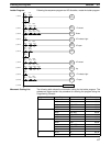
5-1-2 SRM1 Test Run Procedure
1, 2, 3... 1. Power Supply Application
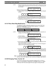
a) Check the SRM1’s power supply voltage and terminal connections.
b) Check the CompoBus/S transmission line terminal connections and the
Slave’s node number and power supply.
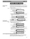
c) Check the I/O devices’ power supply voltage and terminal connections.
d) Turn on the power supply. Turn on the power supply starting from the
Slave.
e) Check that the “PWR” indicator lights.