


Considerations For Operating In Constant Resistance Mode 91
A
Considerations For Operating In Constant Resistance
Mode
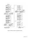
The Agilent Electronic Loads implement Constant Resistance. (CR) mode by using either the CV circuits or CC circuits to
regulate the input. The low range is regulated with the CV circuits, using the input current monitor as the reference.
Therefore, resistance is described by the formula
V
R
I
=
in which input current I is the reference, and voltage at the input terminals, V, is the parameter controlled to determine the
resistance of the load.
The middle and high ranges are regulated with the CC circuits, using the input voltage monitor as the reference. Resistance
is described by the formula
I
V
1
R
=
in which input voltage V is the reference, and current through the input terminals, I, is the parameter controlled to determine
the resistance of the load. The reciprocal of resistance, 1/R, is conductance, G. Therefore, the two highest ranges are best
thought of as constant conductance ranges, with the CC circuit used to control conductance . This affects how the specified
accuracy offset errors (in siemens or 1/ohms, formerly mhos) relate to programmed values (in ohms).
Any offset voltages in the op amps that comprise the load’s regulator circuits become errors at the input terminals of the
load. In both CV and CC modes the offset is constant across the specified operating range, and can be accounted for during
calibration.
The effects of offsets on CR mode accuracy are specified as plus-or-minus constant values in milliohms (low range) or
millisiemens (middle or high ranges), and are less than 1% of full scale. In the two higher ranges of CR mode (the constant
conductance ranges), the effect on the programmed resistance value is not linear over the resistance range, because
resistance is the reciprocal of conductance. Also, because
G=
I
V
the effect of an offset in current (I) on conductance (G) is greater at low input voltages and less for large input voltages.
The electronic load designs are optimized for high-current applications. Therefore, the effects of offsets are more
pronounced at high resistance (very low current) values. This may not represent a problem in typical applications, such as
those in which the load is used to test a power supply. For example, a 5-volt power supply being tested at 1 amp will
require a load resistance of 5 ohms, which is equivalent to 0.2 siemens. The worst-case offset of + 0.008 siemens produces
a resistance of between 4.8 ohms and 5.2 ohms, which represents a 4% error.
By contrast, a 10,000-ohm load connected to a 60-volt power supply will draw only 6 milliamps. Electronic loads are not
designed to regulate such small currents.