


Installation 37
•
Check that the unit has been factory set to the correct line voltage. Refer to the factory check mark on the rear panel
LINE label next to the power connector.
•
Check that the power cord is connected to the ac input socket.
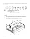
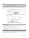
SHOCK HAZARD The power cord provides a chassis ground through a third conductor. Be certain
that your power outlet is of the three-conductor type with the correct pin connected to earth ground
(see Figure 3-1).
•
Check that all sense switches on the modules are set to LCL (depressed).
• Check that the cover is installed with the thumbscrews fully tightened.
Changing Line Voltage
Your Electronic Load can operate with a 100, 120, 220, or 240 Vac input as indicated on the rear panel LINE label. If the
factory check mark on this label does not correspond to your nominal line voltage, change the line voltage as follows:
l. With the mainframe off, disconnect the power cord and remove the cover.
2. Remove the side cover over the GPIB board by removing the handle screws.
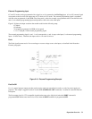
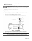
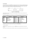
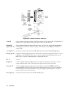
3. Locate the line voltage select switches S202, S203 and S204 in the Electronic Load (see Figure 3-5).
Figure 3-5. Line Voltage Switches
4. Refer to the drawing on the PC board next to the switches and set each switch to the correct line voltage.
5. Replace the side panel and cover. Don’t forget to mark the correct voltage on the rear panel LINE label.
Note Line fuses do not have to be changed when the line voltage selection is changed. The
line fuses will protect the Electronic Load on any of the indicated voltage settings. Line fuses are
discussed in the Service Manual.