Installation 43
Trigger Connector
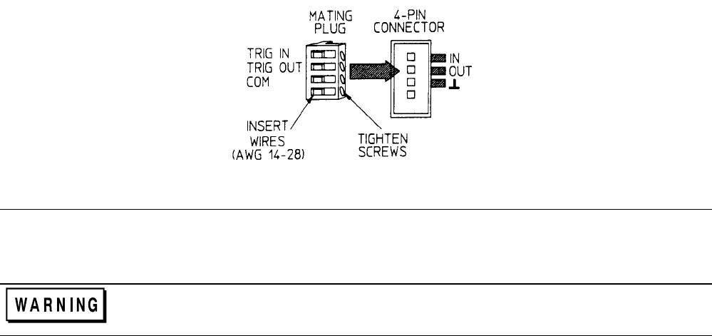
A four-pin connector and a quick connect mating plug (Agilent part number 1252-1488) are provided on each mainframe
for input and output trigger signals (see Figure 3-11). The mating plug is packaged in an envelope that is included with the
mainframe.
Consistent with good engineering practice, all leads connected to the trigger connector should be twisted and shielded to
maintain the instrument’s specified performance.
TRIG IN (pin 1)
A TTL-compatible input that responds to low-level external trigger signals. A trigger applied to
this input can be used to change settings (voltage, current, resistance, etc.), toggle between settings
in transient-toggle mode, or generate a pulse in transient-pulse mode. An external trigger affects
any module that has its external trigger input enabled by the TRIG:SOUR:EXT command.
TRIG OUT (pin 2)
A TTL-compatible output signal that becomes active (low level) whenever the Electronic Load is
triggered with a GPIB command or TRIG IN signal. This signal can be used to trigger external
equipment such as oscilloscopes, digitizers, or another Electronic Load.
Com (pin 3)
Provides the common connection for the trigger signals. This common is directly connected to the
chassis.
Pin 4
Not used
Figure 3-11. Trigger Connector
Application Connections
Wiring Considerations
FIRE HAZARD To satisfy safety requirements, load wires must be heavy enough not to overheat
while carrying the short-circuit output current of the device connected to the Electronic Load. Refer to
Table 3-1 for the ampere capacity of various stranded wire sizes.
Input connections are made to the + and - binding posts on the back of each module. A major consideration in making input
connections is the wire size. The minimum wire size required to prevent overheating may not be large enough to maintain
good regulation. It is recommended that stranded, copper wires be used. The wires should be large enough to limit the
voltage drop to no more than 0.5 V per lead. Table 3-2 gives the maximum load lead length to limit the voltage drop to the
specified limit.


