


Operation Overview 19
Electronic Load are described later in this chapter. The Electronic Load has a status reporting capability to keep track of
pending triggers and other operating conditions. The status reporting capability is described in detail in the Agilent
Electronic Loads Programming Reference Guide.
Transient Current Level
The transient current level can be set at the front panel (
, and ENTRY keys) or via the GPIB
(CURR:TLEV command). The transient current level determines the higher current level when transient operation
(described later in this chapter) is turned on. The module input will switch between the main level and the transient level
when transient operation is turned on.
Software Current Limit
The Electronic Load allows the user to set a current limit (0 to 102% of full scale) for each module via the GPIB
(CURR:PROT command) which will shut down the input if the current limit is exceeded beyond a programmable time
delay. Note that the software current limit is in effect for any mode of operation (not just the CC mode). The software
current limit feature is described later in this chapter under Protection Features.
Slew Rate
Slew rate determines the rate at which the current input to a module changes to a new programmed value. Slew rate can be
set at the front panel (
, and ENTRY keys) or via the GPIB (CURR:SLEW command). This slew rate
remains in effect for the immediate, triggered, and transient level changes previously described.
There are 12 discrete current slew rates within each slewrate range. Any slew rate value can be sent to a module (there are
no upper and lower limits that would cause an error), and a module will automatically select one of the 12 rates that is
closest to the programmed value. The slew rate is rescaled to the closest fit in the 1-of-12 discrete steps if the
current range is changed.
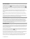
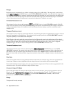
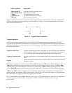
Constant Resistance (CR) Mode
In this mode, the module will sink a current linearly proportional to the input voltage in accordance with the programmed
resistance (see Figure 2-3). The CR mode can be set at the front panel (
, and keys) or via the GPIB
(MODE:RES command). The CR mode parameters are described in the following paragraphs (see also Appendix A).
Figure 2-3. Constant Resistance Mode