


Calibration 75
6
Calibration
Introduction
This chapter describes the calibration procedures for the Agilent 6050A and 6051A Electronic Load mainframe and its
associated modules. Both "A" modules (Agilent Models 60501A-60504A) and "B" modules (Agilent Models 60501B-
60507B) are covered in separate procedures. The Electronic Load should be calibrated annually, or whenever certain
repairs are made (refer to the Service Manual). Calibration is accomplished entirely in software by sending calibration
constants to the Electronic Load via the GPIB. This means that the Electronic Load can be calibrated without removing its
cover, or removing it from its cabinet if rack mounted.
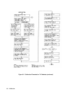
Each module has three DACs that must be calibrated - a main DAC, a readback DAC, and a transient level DAC. Six
ranges must be calibrated for both the main DAC and the transient DAC - a voltage range, a low resistance range, a middle
resistance range, a high resistance range, a low current range, and a high current range. The main DAC requires two
operating points to be calibrated for each range - a high point and a low point. The transient DAC requires only the high
operating point to be calibrated for each range; it uses the same low operating point as the main DAC. Note that the
transient level for the middle and high resistance ranges is lower than the high level of the main DAC.
The readback DAC is only calibrated for the high current range and the voltage range. It also requires two operating points
to be calibrated for each range - a high point and a low point. For the sake of convenience you can use the same values to
calibrate the main and the readback DAC, but you could also use different values to optimize accuracy.
Note All calibration must be done when the Electronic Load is at room temperature.
Equipment Required
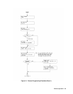
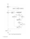
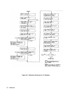
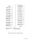
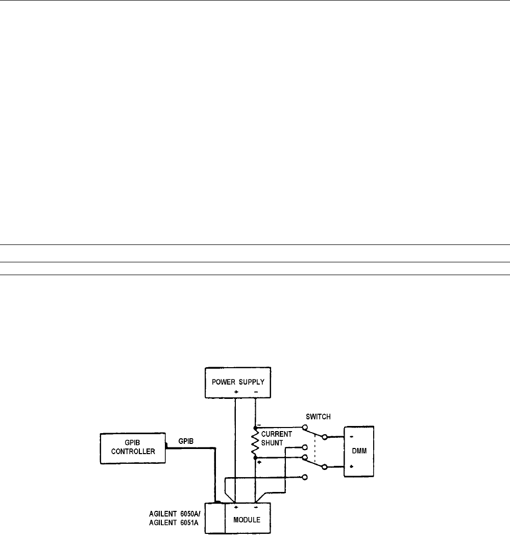
Table 6-1 lists the equipment required for calibration. Note that less accurate and less expensive current shunts may be used
than those listed, but the accuracy to which current and resistance programming as well as readback, can be checked must be
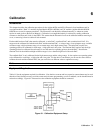
reduced accordingly. Figure 6-1 illustrates how the calibration equipment should be connected.
Figure 6-1. Calibration Equipment Setup