


38 Installation
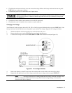
Turn-On/Selftest
Turn on the Electronic Load using the LINE switch on the front panel and observe the display. Immediately after turn-on,
the Electronic Load undergoes a selftest that checks the GPIB interface board as well as the input circuitry of the installed
modules. All of the front panel LCD segments are momentarily activated. When selftest completes, the display should
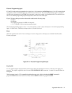
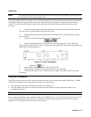
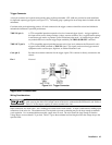
appear about the same as the one shown in Figure 3-6 with the CC annunciator being on.
Figure 3-6. Front Panel Display
After the Electronic Load has passed selftest, connect a power supply to the Electronic Load to test the input circuits as
described under "Power Test".
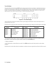
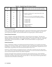
If the Electronic Load fails any portion of the selftest, one of the following error numbers may briefly appear on the display:
GPIB Errors Channel Errors
Display Description Display* Description
ERROR 1 RAM failure 1 ERROR 100 Self test error
ERROR 2 ROM failure 1 ERROR 101 Secondary RAM failure
ERROR 3 GPIB failure 1 ERROR 102 Secondary ROM failure
ERROR 4 Internal trigger failed 1 ERROR 103 Secondary timer trigger failed
ERROR 5 Line trigger failed 1 ERROR 104** Calibration EEprom failed
ERROR 6 Line trigger failed 1 ERROR 105 Main DAC high
ERROR 7 EEprom failed 1 ERROR 106 Main DAC low
1 ERROR 107 Transient DAC high
1 ERROR 108 Transient DAC low
* The applicable channel number is displayed for Multiple Electronic Loads starting with the lowest numbered channel.
Error numbers are not related to the negative numbers returned by the SYST:ERR? query.
** Requires recalibration
Another indication that a selftest failure has occurred is if the ERR annunciator on the display remains on after selftest
completes.
If the Electronic Load has failed selftest, the mainframe or module to the nearest Agilent Sales and Service Office for repair.