Operation Overview 29
Overvoltage
The overvoltage protection circuit is set at a predetermined voltage, which cannot be changed. If the overvoltage circuit has
tripped, the module will attempt to limit the voltage by drawing current from the DC source. The module limits the value of
current drawn such that the resulting power is within the power rating. The overvoltage (OV) and voltage fault (VF) status
register bits are set when the OV condition occurs, and will remain set until they are reset as previously described.
An overvoltage condition does not cause the module’s input to be turned off . However, a Fault signal output at the
module’s rear-panel control connector will indicate when either an overvoltage condition or a reverse voltage condition has
occurred. The Fault signal is latched true (high TTL level) when the VF bit in the status register goes true. The Fault
output signal (see Chapter 3 - Installation) can be used to trip an external circuit breaker or control a relay (e.g., Agilent
59510A Relay Accessory) in order to disconnect the Electronic Load input from the source it is testing when an overvoltage
or a reverse voltage condition occurs.
Overcurrent
The Electronic Load includes both hardware and software overcurrent protection features.
Hardware. When operating in the CR or CV mode, it is possible for a module to attempt to sink more current than it is
rated for.
Under this condition, the load current will be limited by a current limit circuit, which is set at a value slightly above the
current rating of the module. It protects both the Electronic Load and the device under test from operating too far beyond
specified limits. The hardware current limit circuit does not turn the module’s input off. The overcurrent (OC) bit in the
status register is set when an OC condition occurs, and is reset when the OC condition is removed.
Software. In addition to the hardware overcurrent protection circuit, the Electronic Load allows the user to define a current
protection limit in software which will shut down a module’s input if the limit is exceeded. This feature can only be
programmed via the GPIB. It is turned on/off using the CURR:PROT:STATE ON|OFF command. The software current
limit level (in amps) is set using the CURR:PROT command. A programmable delay (in seconds) before trip is also
provided with the CURR:PROT:DEL command. If the software overcurrent limit is exceeded and persists beyond the
specified delay time, the module is turned off. Also, for these conditions, the OC and PS (protection shutdown) status
register bits are set and will remain set until the OC condition is removed and the bits are reset as previously described.
Overpower
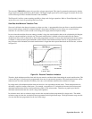
A load module’s response to an overpower condition depends on whether the module was operating with the nominal power
limit or the extended power limit when the overpower condition occurred.
Nominal Power Limit. The nominal power-limit boundary is set by software that monitors the input current and voltage.
If the input power exceeds the nominal power limit, the load module sets the overpower status bit, which will reset if the
overpower condition ceases. If the overpower condition persists for 3 seconds, the load module’s input circuit turns off, and
the OP and PS status bits are both latched on. The input circuit remains off, and the OP and PS status bits remain set, until
protection clear occurs. Of course, if the overpower condition is not corrected, the load will turn off again.
Extended Power Limit. The extended power-limit boundary is set by hardware circuits. This hardware power-limit circuit
can be activated by any of three conditions:
1. If an overpower condition occurs while the module is operating in the extended power area.
2. During certain large programmed changes
3. If the nominal power limit is exceeded (the software limit sets the OP bit and starts the 3-second timer, but
does limit the input power)


