


Operation Overview 15
2
Operation Overview
Introduction
The Agilent 6050A and Agilent 6051A Multiple Input Electronic Load Mainframes are used for design, manufacturing, and
evaluation of dc power supplies, batteries, and power components. Other applications include use as a power circuit
breaker or crowbar, high-current function or pulse generator, fuel-cell and photovoltaic cell test, and de-energizing
superconducting magnets.
The mainframe contains six (two) slots for load modules. Load modules occupy either 1 or 2 slots, depending on the power
rating of the module. The mainframe can dissipate up to 300 watts per slot, to a total of 1800 (600) watts for a fully loaded
mainframe. An individual module may have either 1 or 2 channels, each of which has its own channel number. Each
module contains its own input connectors. The mainframe contains a processor, GPIB connector and interface circuits,
trigger circuits, front-panel keypad and display, and other circuits common to all the load modules.
Each module can operate independently in constant current (CC) mode, constant voltage (CV) mode , or constant resistance
(CR) mode. In addition, each input can be turned on or off (open circuit) or short circuited.
Features include built-in GPIB interface and built-in pulse generator, both standard. Pulse mode allows dynamic testing of
power supplies and components, without giving the device under test time to heat up. The flexible pulse mode provides six
triggering methods, allowing synchronization with a wide variety of events. A Save/Recall feature allows you to save up to 7
complete instrument setups, one of which can be saved in non-volatile memory so that it is recalled automatically at power-
on. Also standard is GPIB readback of actual input voltage and current, and extensive protection and status reporting
capability.
The mainframe contains two (one) cooling fans whose speed automatically increases or decreases as the module
temperatures rise and fall. This feature reduces overall noise level because the fans do not run at maximum speed at all
times.
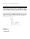
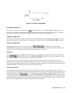
The input power rating curve for each module is shown in the module-specific pages. See the extended power paragraphs in
this section for a description of the power rating curves. Note that regardless of a module’s power rating, input current is
derated linearly from 2 volts down to 0 volts.
Each load module can be individually controlled either via GPIB or locally via the front panel. Once a channel is selected
or addressed, all subsequent commands go to that channel until another channel is selected or addressed. Operation of all
models is similar, regardless of power ratings. Therefore, the operating instructions given in this manual are generic, and
apply to all modules. The module-specific pages provided with each module include specifications and other information
pertinent just to a particular model. Some examples described here may use values that are not appropriate for your module,
but the example is valid. Some descriptions refer to ranges, limits, full-scale values, and similar terms (for example, low
range and high range). Refer to the module-specific pages provided with each module for the actual values.
Programs written for the Agilent 6060 series of single Electronic Loads can be used with the multiple loads, easing program
development for applications using various members of the Agilent Electronic Load family. (Triggering via the ac line
frequency or the load’s internal timer is available only in the multiple load mainframe.)
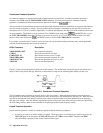
If your application requires a greater power or current capacity than one module can provide, load modules can be
connected in parallel in CC or CR mode.