


30 Operation Overview
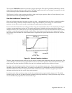
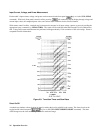
If the hardware power-limit circuit becomes active, it attempts to limit power by limiting the current drawn by the load.
Once the power has been returned to the safe operating area, the protective circuit allows the current to rise again. This
protective sequence can turn on and off (approximately 5% of full scale peak-to-peak) at rates from 2 kHz to 12 kHz. It will
continue until the overpower condition ceases, or the module’s heatsink temperature rises enough to cause the module to
impose the nominal power limit. With the nominal power limit in effect, the module’s input circuit will open after the 3-
second delay. Note that this oscillation is a design feature that protects your instrument while preventing nuisance
shutdowns caused by transient conditions.
Overtemperature
Each module has an overtemperature (OT) protection circuit which will turn off the input if the internal temperature exceeds
safe limits. If the OT circuit activates, the OT and PS status register bits are set and will remain set until they are reset. If
the OT condition still exists when the reset is executed, the module’s input will remain off. You must wait until the module
cools down before you can reset the OT circuit. The fan(s) will continue to operate to cool the unit as quickly as possible.
Reverse Voltage
This feature protects the load module in case the input dc voltage lines are connected with the wrong
polarity. If a reverse voltage (RV) condition is detected, turn off power to the dc source and the
Electronic Load and make the correct connections.
The Electronic Load conducts reverse current when the polarity of the DC source connection is incorrect. The maximum
safe reverse current is specified in the module-specific pages. The reverse voltage (RV) and voltage fault (VF) bits in the
status register are set when reverse voltage is applied. When the reverse voltage is removed the RV bit is cleared.
However, the VF bit remains set until it is reset. As previously described, the Fault output signal at the control connector
tracks the state of the VF bit. The Fault signal can be used to control an external relay in order to disconnect the module
from the dc source if an RV condition occurs.
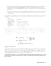
Control Connector
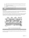
Each module has a 10-pin connector mounted on its rear panel. These signals are described in the following paragraphs.
See Chapter 3 for connection details.
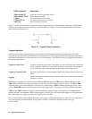
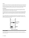
Remote Sensing
The remote sensing inputs, + S and - S, can be used in CV or CR modes. By eliminating the effect of the inevitable voltage
drop in the load leads, remote sensing provides greater accuracy by allowing the load to regulate directly at the source’s
output terminals, as well as measure the voltage there.
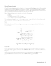
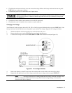
Monitor Outputs
The IMON and VMON output signals indicate the input current and voltage. A 0-to-10V signal at the appropriate output
indicates the zero-to-full scale input current or voltage. An external DVM or oscilloscope can be connected to monitor the
input voltage and current.