


Operation Overview 31
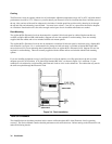
External Programming Input
CC and CV modes can be programmed with a signal (ac or dc) connected to the Ext Prog input. A 0-to-10V external signal
corresponds to the 0-to-full scale input range in CV mode or in CC mode. The external programming signal is combined
with the value programmed via the GPIB or the front panel, so that, for example, a programmed value of one-half full scale
and a 5-volt external programming input would produce a full-scale value at the input.
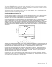
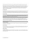
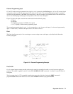
Figure 2-10 shows the input waveform that would result from the following setup:
CC Mode
60 A Range
20 A Input (programmed via GPIB or front panel)
± 1 V (2 V pk-pk) 1 kHz external programming signal
The external programming signal (+ and - 1 volt) corresponds to + and - 6 amps at the input (1 volt external programming
input = 1/10 full scale). Therefore, the input varies
±
6 A at the 20 A level.
Fault
The Fault signal becomes active if an overvoltage or reverse voltage occurs at the input, as described in the Protection
Features paragraphs.
Figure 2-10. External Programming Example
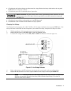
Port On/Off
Port is a general purpose output port that can be used to control an external device such as a relay for power supply test
purposes. The output is toggled on and off via the GPIB (PORT0 ON | OFF command). It cannot be controlled from the
front panel.
The Port output signal is a TTL compatible signal that becomes active (high level) when the PORT command is
programmed ON and becomes inactive low level) when the PORT command is programmed OFF.