


Installation 41
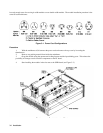
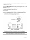
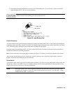
3. Hand tighten the adjustment knob to secure the wire in the binding post. If you are using a slotted screwdriver,
tighten the knob to 8 in. -lbf for a secure connection..
Do not use lubricants or contact cleaners on the binding posts. Certain chemical agents can damage the
LEXAN material of the binding post, causing the part to fail.
Figure 3-9. Input Binding Post
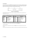
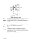
Control Connector
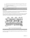
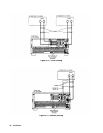
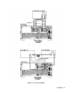
A ten-pin connector and a quick-disconnect mating plug (Agilent part number 0360-2345) are provided on each module for
connecting remote sense leads, external V/I monitors, an external programming input, and external control lines (see Figure
3-10). The mating plug is packaged in an envelope that is included with the module.
Consistent with good engineering practice, all leads connected to the control connector should be twisted and shielded to
maintain the instrument’s specified performance.
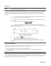
Make all wire connections to the mating plug as required (see Figure 3-10) before you install the connector in the module.
After you have finished making all wire connections, open the connector cover on the back of the module as shown in
Figure 3-10 and insert the mating plug into the connector.
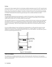
Sense Switch
A local/remote sense switch is provided on each module (see Figure 3-10). Unless you are using remote sensing, make sure
that the sense switch is set to LCL (depressed). Remote sensing is used in certain applications to achieve greater accuracy
(refer to "Remote Sense Connections" for more information).
Note If the sense switch is set to remote operation without having sense leads connected to the sense inputs,
the module will continue to work in CC mode, but the input will turn off in CV and CR mode. Voltage
readback will not work in any mode.