


16 Operation Overview
Front Panel Description
The front panel includes a 12-character alphanumeric display, 11 status indicators, and four groups of keypads. Ordinarily
the alphanumeric display shows the number of the channel presently under front-panel control, and the input voltage and
current of that channel. By using the
key you can sequentially display input power, programming error codes, and
protection-circuit status. If any protection circuits are active, that status will be displayed first when you use the
key. If you change channels via the front panel, any fault information will be displayed first for the new channel. Then you
can key through the display in the normal sequence. The alphanumeric display also shows what function is being performed
when you use the keypads.
The display also includes 11 annunciators that point to the 11 status labels printed on the front panel. The Constant
Current, Constant Resistance, Constant Voltage, Transient, and Unregulated status annunciators are specific to the channel
displayed. The Protection, Error, Shift, Remote, Address, and Service ReQuest status annunciators are channel
independent.
Four of the keys perform two functions, with the alternative function labeled in blue above the key. The alternative
function is selected by first pressing the blue (shift) key, which turns on the Shift annunciator and enables the alternative
function.
Note that the front-panel display operates independently from the GPIB CHANNEL command. In other words, you can
select a channel locally (front panel) for which the display will show the input voltage and current, and the controller can
subsequently send commands to other channels without changing the channel being displayed.
Remote Programming
Commands sent to the Electronic Load via GPIB are decoded by the mainframe microprocessor, which detects syntax and
range errors. The mainframe processor also prescales data sent to the modules, and maintains status registers for each
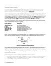
module. Three commands have aliases for compatibility with other HPSL instruments. MODE can also be called
FUNCtion, INPut can also be called OUTPut, and CHANnel can also be called INSTrument. OUTPut and INSTrument
would typically be used if you want your program to refer to the load modules in terms of the device or instrument under
test. Be careful if using INSTrument for CHANnel in systems that have more than one Electronic Load mainframe;
someone looking at the listing in the future may be misled.
Local/Remote Control
Local (front panel) control is in effect immediately after power is applied. The front panel keypad and display allow manual
control of each individual module when the Electronic Load is used in bench test applications. Remote (computer) control
goes into effect (front panel Rmt annunciator is on) as soon as the mainframe receives a command via the GPIB. A built-in
GPIB interface and HPSL compatible commands allow control and readback of all functions when the Electronic Load is
used in computer controlled applications.
With remote control in effect, only the computer can control the Electronic Load; the front panel keypad has no effect. You
can, however, still use the front panel display to view the input voltage and current readings. You can return the Electronic
Load to local control from remote control by pressing
. This will return the Electronic Load to local control, unless
the local-lockout command has been received from the GPIB computer.
Most of the functions that can be performed remotely over the GPIB can also be performed locally at the front panel. The
names on the keys reflect the HPSL commands that are used to program the various functions. Consequently, learning to
operate the Electronic Load from the front panel will aid you when you start to write computer programs.
Details of local operation are covered in Chapter 4 - Local Operation and fundamentals of remote programming are given
in Chapter 5 - Remote Operation. Complete HPSL programming details are given in the Agilent Electronic Loads
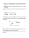
Programming Reference Guide. The remaining paragraphs in this chapter describe the operating modes, transient