Introduction
HP NonStop S-Series Hardware Installation and FastPath Guide—541880-001
1-24
Installation Overview
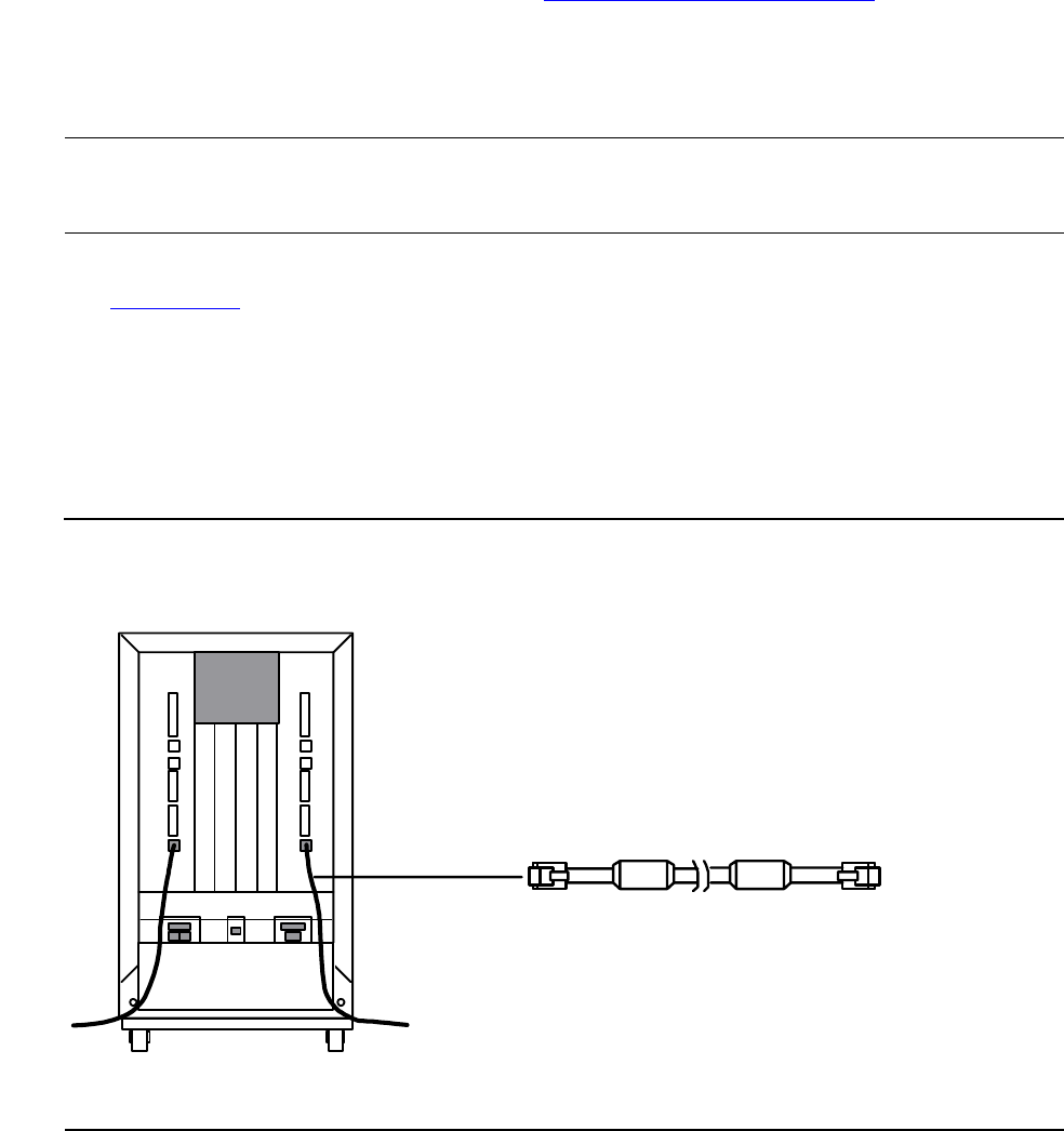
Power-On Cables
Power-on cables carry the power-on signal from one PMF CRU or IOMF CRU to
another, allowing you to power on all system enclosures in a system from one push
button.
•
Power-on cables have an RJ-11 connector at each end as illustrated in
Figure 1-10.
•
One power-on cable is required for each system enclosure.
•
Power-on cables can be 8.2 feet (2.5 meters) or 23.0 feet (7.0 meters) long.
•
The cables and enclosures must form a continuous ring so that each enclosure
can deliver the power-on signal to the next enclosure.
For Information About See
When to use specific cable lengths NonStop S-Series Planning and Configuration Guide
Where to install the power-on cables
•
Your Installation Document Checklist
•
Appendix C, Power-On Cabling
Note. IOAM enclosures do not require power-on cables. For more information, your service
provider can refer to the Modular I/O Installation and Configuration Guide located in the NTL
Hardware Service and Maintenance Collection in the Support and Service Library.
Figure 1-10. Power-On Cable Connectors
VST703.vsd
System Enclosure
(Service Side)
Power-On Cable


