


!
!
6-3SectionHandling
87
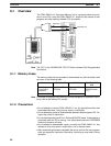
Lift up the lock lever and detach the EEPROM.
6-3-2 PC Connections
Caution Mount the EEPROM to the CPM1-EMU01-V1 before connecting the
CPM1-EMU01-V1 to the PC.
Caution Do not disconnect the CPM1-EMU01-V1 from the PC when the indicator is blink-
ing green.
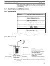
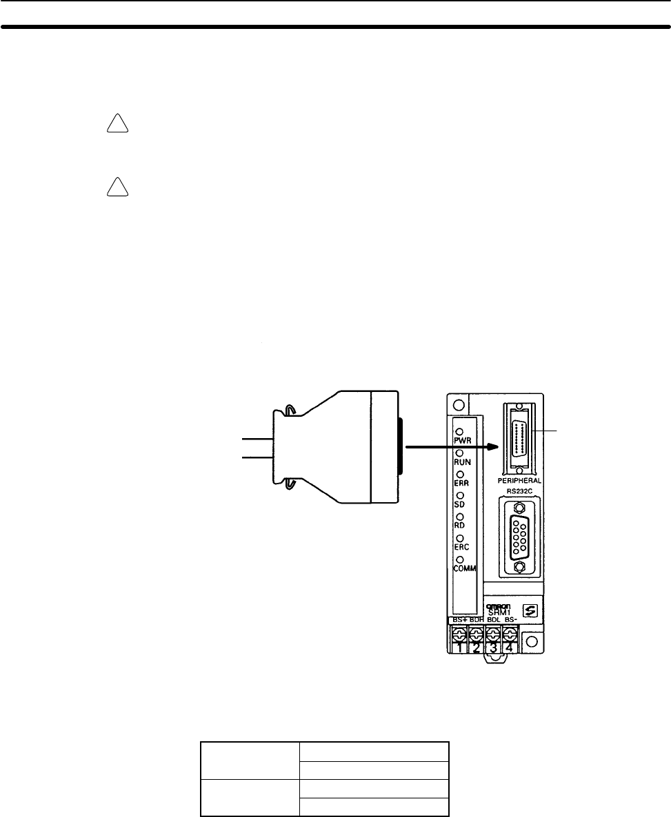
When connecting to the CPM1, CPM1A, CPM2A, CQM1 or SRM1 (-V2),insert
the connector into the peripheral port making sure that the connector is oriented
correctly.
• Insert the connector until it securely locks into place.
• Connections are not possible to the RS-232C port or any other port.
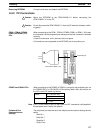
Connection to SRM1 (-V2)
Peripheral port
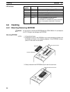
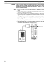
When connecting to the CPM2C or CQM1H, connect to the peripheral port via
the CPM2C-CN111 or CS1W-CN114 Connecting Cable. Also, set the pins on
the CPU Unit’s DIP switch as follows:
CPM2C
Pin 1: ON (see note)
Pin 2: ON
CQM1H
Pin 5: ON (see note)
Pin 7: ON
Note If pin 1 on the CPM2C or pin 5 on the CQM1H is OFF, connection is still possible if
the peripheral port is set to the defaults.
The peripheral port must be set to the default communications settings shown
below.
Start bit: 1
Data bits: 7
Stop bits: 2
Parity: Even
Removing EEPROM
CPM1, CPM1A, CPM2A,
CQM1, and SRM1 (-V2)
PCs
CPM2C and CQM1H PCs
Peripheral Port
Communications
Settings