


1-2SectionSystem Configuration
4
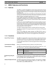
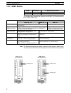
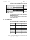
1-2-2 SRM1 Models
Model RS-232C port PT programming functions
SRM1-C01-V2 No No
SRM1-C02-V2 Yes Yes
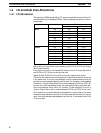
The following table compares the functions in the SRM1(-V2) PCs with the func-
tions in earlier SRM1 PCs.
Function
SRM1 models
SRM1-C0j-V2 SRM1-C0j-V1 SRM1-C0j
Data backup Backed up by a lithium battery with a minimum lifetime of 10
years at 25_C.
Capacitor backup
Programming
Console functions
Programming can be performed through a Programming
Console connected to the peripheral port or an OMRON PT
connected to the RS-232C port.
Programming can be performed
through a Programming Console
connected to the peripheral port.
Data processing Bit data (ON/OFF for 16 bits) and 16-bit
analog data from Analog Units
Bit data (ON/OFF status of bits)
Communications High-speed communications (previous
mode) or long-distance communications
mode
High-speed communications mode (previous
mode) only.
Connections with
host devices
Host Link, no-protocol, 1:1 NT Link, 1:N NT
Link, and 1:1 PC Link communications
Host Link, no-protocol, 1:1 NT Link, and 1:1 PC
Link communications
Instructions The instructions in earlier SRM1 PCs plus
the following instructions:
NEG(––), PID(––), SCL(66), and ZCP(––)
Basic instructions: 14
Special instructions: 77 (123 variations)
Note The Analog Terminal can be used as a slave only with version-2 models. Incor-
rect data may be transferred if an Analog Terminal is used with the wrong model.
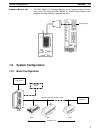
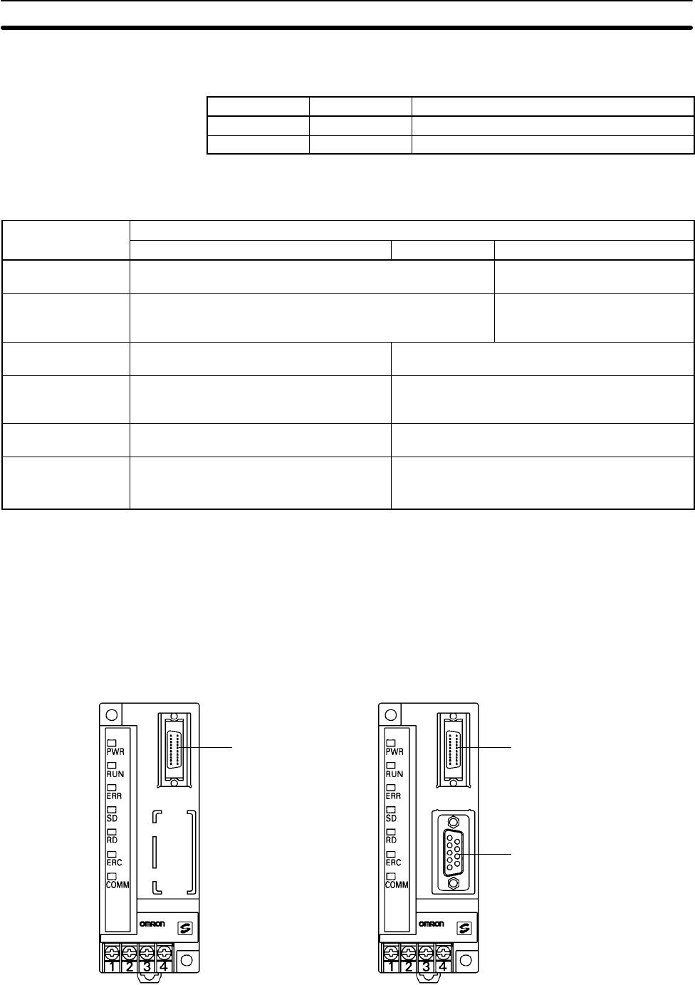
Peripheral port
SRM1-C01-V2
(No RS-232C port)
Peripheral port
SRM1-C02-V2
(With RS-232C port)
RS-232C port