


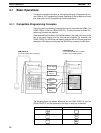
4-1SectionBasic Operations
35
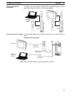
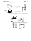
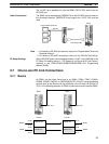
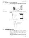
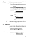
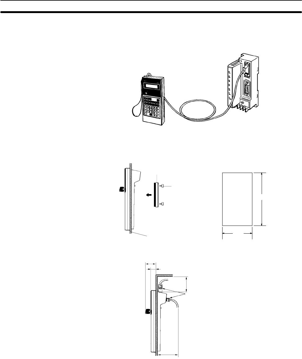
4-1-2 Connecting the Programming Console
Connect the Programming Console’s connecting cable to the SRM1’s peripher-
al port, as shown below.
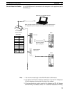
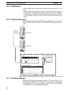
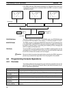
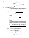
Panel Installation The C200H-PRO27-E Programming Console can be installed in a control panel
as shown in the following diagram. (The C200H-ATT01 Mounting Bracket is sold
separately.)
Mounting Bracket
Two screws
Panel thickness: 1.0 to 3.2 mm
Mounting hole dimensions
(DIN43700 standards)
186
+1.1
–0
92
+0.8
–0
Allow at least 80 mm for the cable connector above the Programming Console.
About 70 mm is required.
At least 80 mm is required.
Either connector may
be used.
37
15
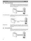
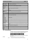
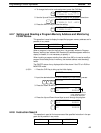
4-1-3 Changing the SRM1’s Mode
Once the Programming Console has been connected, its mode switch can be
used to change the SRM1’s PC mode. The mode display (<PROGRAM>,
<MONITOR>, or <RUN>) will appear on the Programming Console screen.
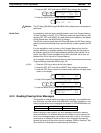
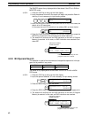
• No key operations can be performed while the mode display is displayed on
the Programming Console screen. Press CLR to clear the display so that key
operations can be performed.
• If the SHIFT Key is pressed while the mode switch is turned, the original dis-
play will remain on the Programming Console’s screen and the mode display
won’t appear.