


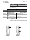
1-4SectionI/O and Data Area Allocations
8
1-4 I/O and Data Area Allocations
1-4-1 I/O Allocations
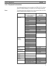
The input bits of SRM1 words 000 to 007, and the output bits of words 010 to 017,
are allocated to the CompoBus/S Slave. These allocations are shown in the fol-
lowing table.
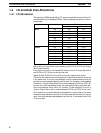
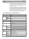
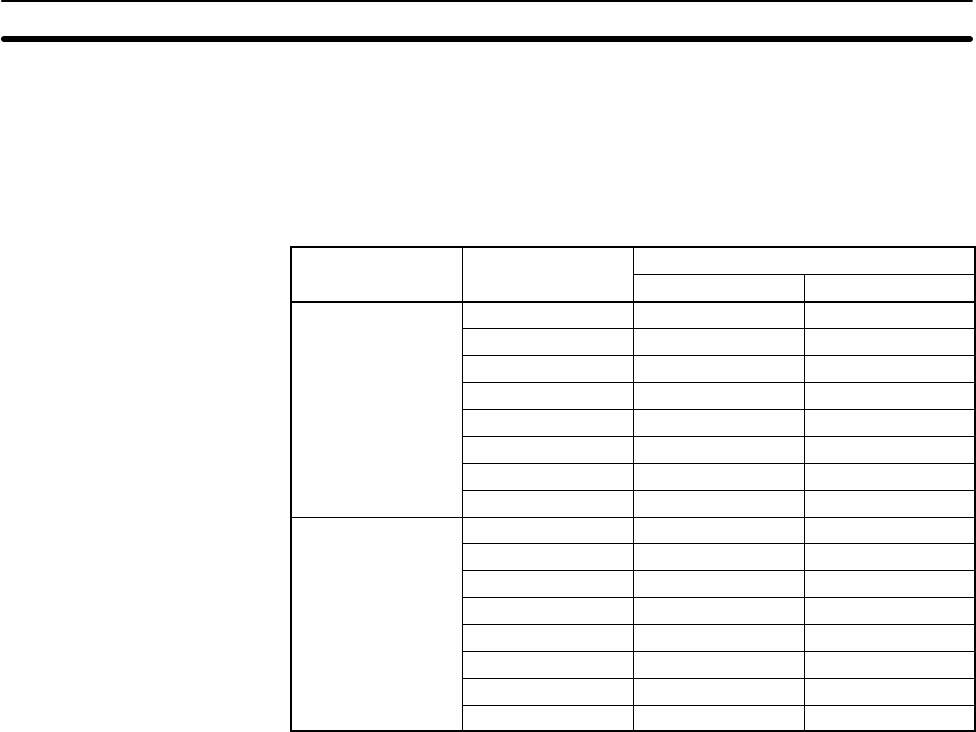
I/O Word address
Bits
15 to 08 07 to 00
Inputs
000 IN1 IN0
001 IN3 IN2
002 IN5 IN4
003 IN7 IN6
004 IN9 IN8
005 IN11 IN10
006 IN13 IN12
007 IN15 IN14
Outputs
010 OUT1 OUT0
011 OUT3 OUT2
012 OUT5 OUT4
013 OUT7 OUT6
014 OUT9 OUT8
015 OUT11 OUT10
016 OUT13 OUT12
017 OUT15 OUT14
IN0 to IN15 are Input Slave node numbers, and OUT0 to OUT15 are Output
Slave node numbers.
If the maximum number of CompoBus/S devices is set to 16, then IN8 to IN15
and OUT8 to OUT15 can be used as work bits.
Words IR 008, IR 009, IR 018, and IR 019 can be used as work words.
The bits for two node number are allocated to 16-point Slaves so that all bits are
in the same word. If an even node address is set, the node address that is set
and the next node address following it will be used. For example, if node address
6 is set for a 16-point Output Slave, bits for node addresses OUT6 and OUT7 will
be used. If an odd node address is set, the node address that is set and the pre-
vious node address will be used. For example, if node address 3 is set for a
16-point Output Slave, bits for node addresses OUT2 and OUT3 will be used.
All of the bits for one node address are allocated to a 4-point Slave. If an even
numbered node address is set, bits 00 to 03 are used and bits 04 to 07 are not
used. If an odd numbered node address is set, bits 8 to 11 are used and bits 12 to
15 are not used.