


88
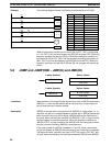
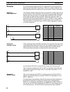
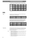
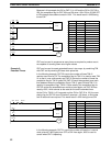
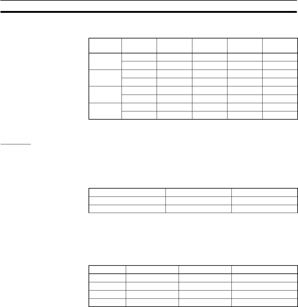
Timer ranges are set in the output words as shown in the following table.
Timer Output
word bit
0.1 to 1s 1 to 10s 10 to 60s 1 to 10m
T
0
08 OFF ON OFF ON
09 OFF OFF ON ON
T
1
10 OFF ON OFF ON
11 OFF OFF ON ON
T
2
12 OFF ON OFF ON
13 OFF OFF ON ON
T
3
14 OFF ON OFF ON
15 OFF ON OFF ON
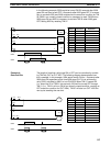
Example
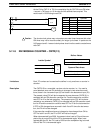
This example uses an Analog Timer Unit connected to a C28K CPU. Word
allocations are shown in the following table.
Unit Input word Output word
CPU 00 01
Analog Timer Unit 02 03
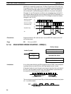
All four time’s are used. Times for two of them are adjusted on the variable
resistors provided on the Analog Timer Unit. The other two times are ad-
justed using external resistors. These adjustments are made as follows. Re-
fer to the
Analog Timer Unit Installation Guide
for hardware details.
Timer SV Range Resistor adjustment
T
0
Approx. 0.6 s 0.1 to 1 s 6/10th turn clockwise
T
1
Approx. 3 s 1 to 10 s 3/10th turn clockwise
T
2
Approx. 2.6 s 10 to 60 s 2/10th turn clockwise
T
3
Approx. 8 min 1 to 10 min 8/10th turn clockwise
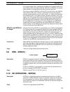
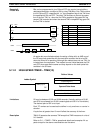
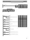
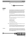
The following program sections are used to set up the required data and pro-
duce outputs from the four timers. The first section moves E400 into IR 06 to
set the desired ranges (see table above). The second program section
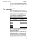
achieves the following operation.
1, 2, 3...
1. IR 0500 is turned ON approximately 0.6 seconds after IR 0002 turns ON
as the result of the action of T
0
.
2. IR 0501 is turned ON approximately 3 seconds after IR 0003 turns ON
as the result of the action of T
1
.
3. IR 0502 is turned ON approximately 20 seconds after IR 0004 turns ON
as the result of the action of T
2
.
4. IR 0503 is turned ON approximately 8 minutes after IR 0004 turns ON
as the result of the action of T
3
.
Setup
Programming
Timer and Counter Instructions Section 5-11