


33
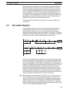
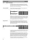
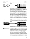
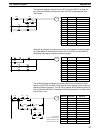
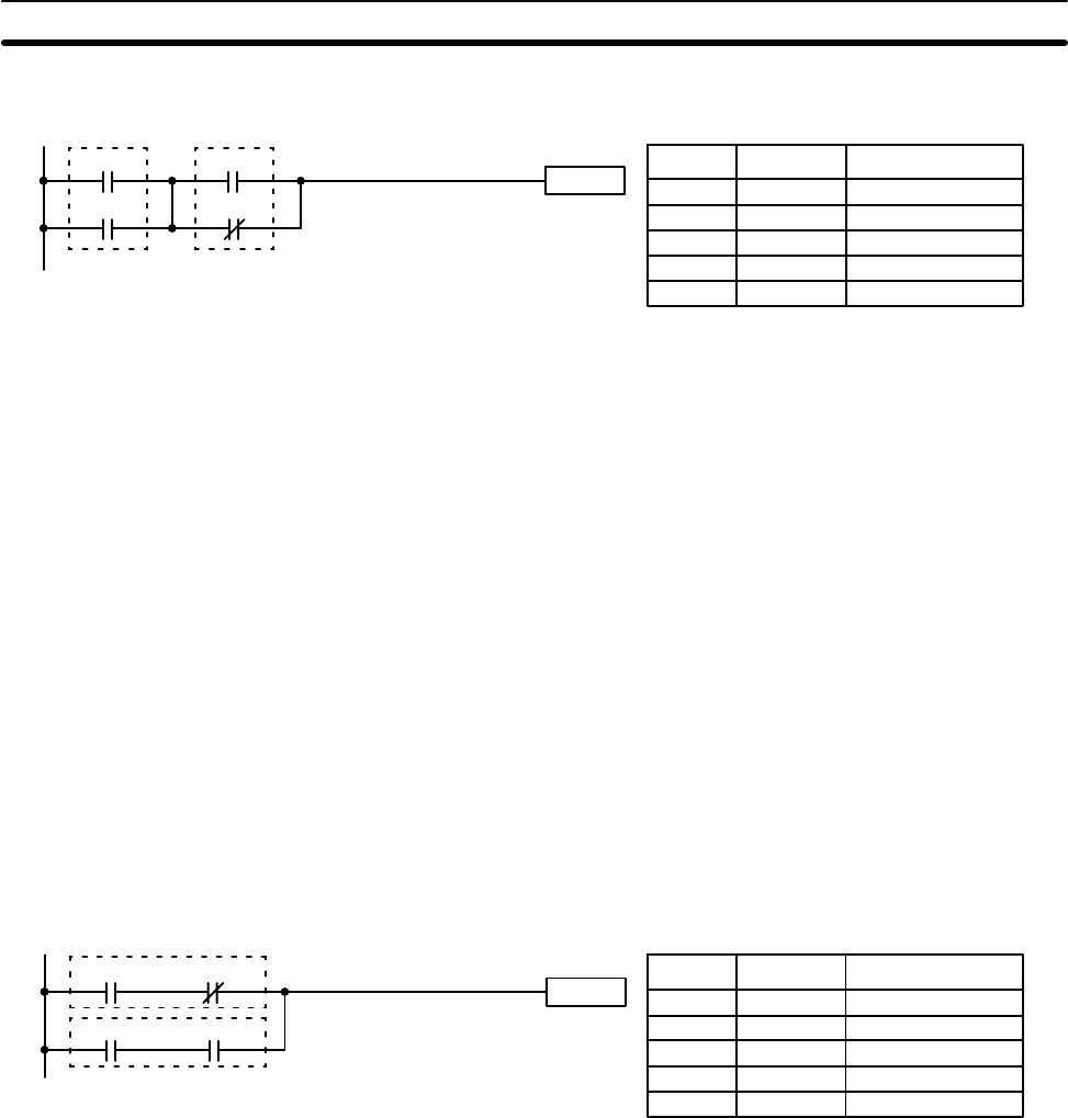
Although simple in appearance, the diagram below requires an AND LOAD
instruction.
Instruction
0002
0003
0000
0001
Address Instruction Operands
0000 LD 0000
0001 OR 0001
0002 LD 0002
0003 OR NOT 0003
0004 AND LD ---
The two logic blocks are indicated by dotted lines. Studying this example
shows that an ON execution condition would be produced when both 1)
either of the conditions in the left logic block was ON (i.e., when either 0000
or 0001 was ON) and 2) either of the conditions in the right logic block was
ON (i.e., when either 0002 was ON or 0003 was OFF).
Analyzing the diagram in terms of instructions, the condition at 0000 would
be a LOAD instruction and the condition below it would be an OR instruction
between the status of 0000 and that of 0001. The condition at 0002 would be
another LOAD instruction and the condition below this would be an OR NOT
instruction, i.e., an OR between the status or 0002 and the inverse of the
status of 0003. To arrive at the execution condition for the instruction at the
right, the logical AND of the execution conditions resulting from these two
blocks would have to be taken. AND LOAD allows us to do this. AND LOAD
always takes an AND between the current execution condition and the last
unused execution condition. An unused execution condition is produced by
using the LOAD or LOAD NOT instruction for any but the first condition on an
instruction line.
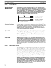
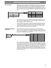
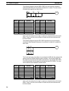
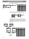
Although we’ll not describe it in detail, the following diagram would require an
OR LOAD instruction between the top logic block and the bottom logic block.
An ON execution condition would be produced for the instruction at the right
either when 0000 was ON and 0001 was OFF or when 0002 and 0003 were
both ON.
Instruction
0000 0001
0002 0003
Address Instruction Operands
0000 LD 0000
0001 AND NOT 0001
0002 LD 0002
0003 AND 0003
0004 OR LD ---
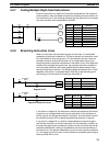
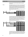
Naturally, some diagrams will require both AND LOAD and OR LOAD instruc-
tions.
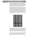
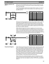
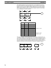
To code diagrams with logic block instructions in series, the diagram must be
divided into logic blocks. Each block is coded using a LOAD instruction to
code the first condition, and then AND LOAD or OR LOAD is used to logically
combine the blocks. With both AND LOAD and OR LOAD there are two ways
to achieve this. One is to code the logic block instruction after the first two
blocks and then after each additional block. The other is to code all of the
blocks to be combined, starting each block with LOAD or LOAD NOT, and
then to code the logic block instructions which combine them. In this case,
the instructions for the last pair of blocks should be combined first, and then
each preceding block should be combined, working progressively back to the
first block. Although either of these methods will produce exactly the same
result, the second method, that of coding all logic block instructions together,
can be used only if eight or fewer blocks are being combined, i.e., if seven or
fewer logic block instructions are required.
AND LOAD
OR LOAD
Logic Block Instructions in
Series
The Ladder Diagram Section 4-3