94
CNTR(12) is reset with a reset input, R. When R goes from OFF to ON, the
PV is reset to zero. The PV will not be incremented or decremented while R
is ON. Counting will begin again when R goes OFF. The PV for CNTR(12)
will not be reset in interlocked program sections or for power interruptions.
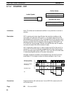
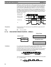
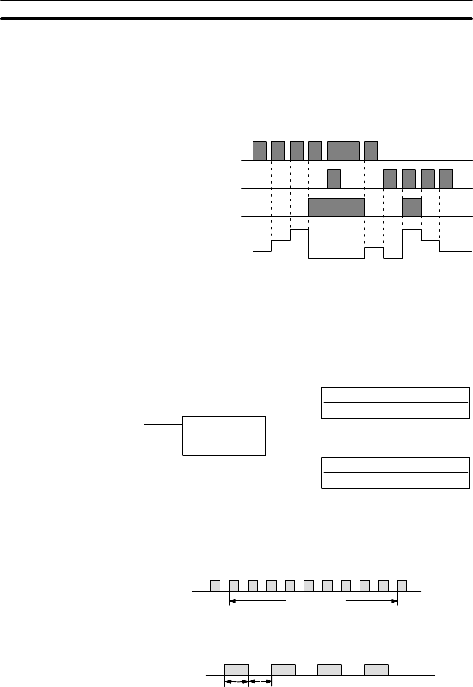
Changes in II and DI execution conditions, the completion flag, and the PV
are illustrated below starting from part way through CNTR(12) operation (i.e.,
when reset, counting begins from zero). PV line height is meant to indicate
changes in the PV only.
Execution condition
on increment (II)
Execution condition
on decrement (DI)
ON
OFF
ON
OFF
Completion flag
ON
OFF
PV
SV
SV - 1
SV - 2
0001
0000
0000
SV
SV - 1
SV - 2
Program execution will continue even if a non-BCD SV is used, but the SV
will not be correct.
ER: SV is not in BCD.
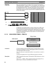
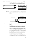
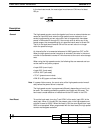
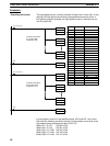
5-11-6 HIGH-SPEED DRUM COUNTER – HDM(61)
N: TC number
Must be 47
Ladder Symbol
Definer Values
R: Result word
IR, HR, DM
Operand Data Areas
HDM(61) N
R
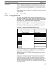
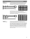
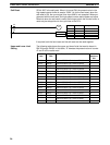
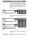
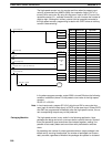
If any of the lower limits for the DM ranges are set to “0000,” the correspond-
ing output bits are turned ON when the high-speed counter is reset.
If the time it takes to count through some range is less than the cycle time of
the CPU, the high-speed counter may count past between cycles and thus
the output bit for this range may not be turned ON.
Counting
Time
Lower Limit Upper Limit
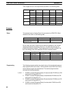
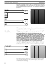
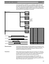
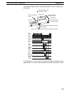
The count signal must be at least 250 µs (2 kHz) wide and have a duty factor
of 1:1, as shown below.
250 µS 250 µS
Input
0000
Precautions
Flags
Limitations
Timer and Counter Instructions Section 5-11


