


86
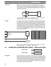
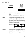
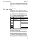
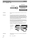
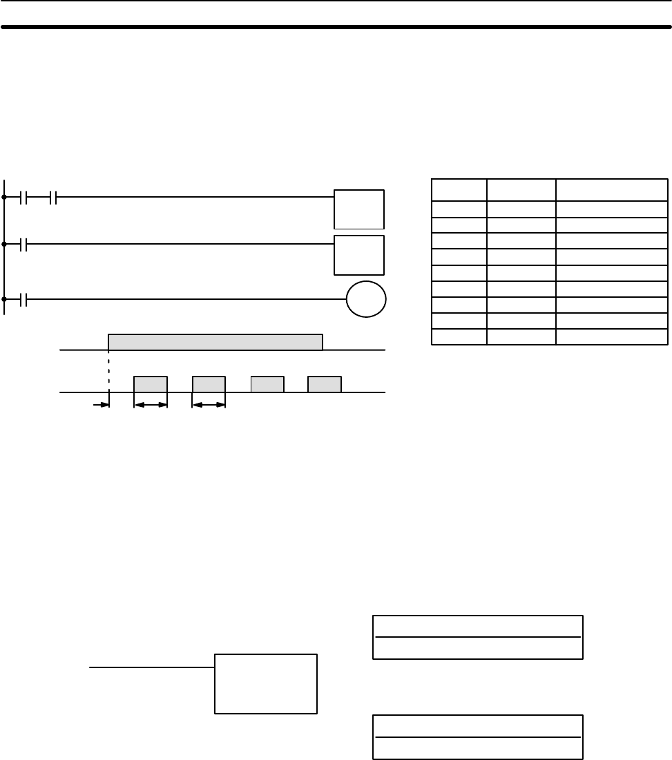
Bits can be programmed to turn ON and OFF at a regular interval while a
designated execution condition is ON by using TIM twice. One TIM functions
to turn ON and OFF a specified bit, i.e., the completion flag of this TIM turns
the specified bit ON and OFF. The other TIM functions to control the opera-
tion of the first TIM, i.e., when the first TIM’s completion flag goes ON, the
second TIM is started and when the second TIM’s completion flag goes ON,
the first TIM is started.
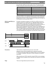
0000
TIM 02
TIM 01
TIM 01
0205
0000
0205
1.5 s1.0 s 1.5 s1.0 s
Address Instruction Operands
0000 LD 0000
0001 AND TIM 02
0002 TIM 01
# 0010
0003 LD TIM 01
0004 TIM 02
# 0015
0005 LD TIM 01
0006 OUT 0205
TIM 02
#0015
TIM 01
#0010
1.0 s
1.5 s
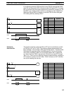
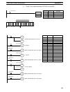
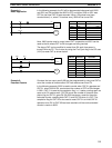
An easier but more limited method of creating a flicker bit is to AND one of
the SR area clock pulse bits with the execution condition that is to be ON
when the flicker bit is operating. Although this method does not use TIM, it is
included here for comparison. This method is more limited because the ON
and OFF times must be the same and they depend on the clock pulse bits
available in the SR area.
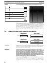
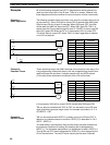
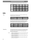
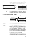
5-11-2 HIGH-SPEED TIMER – TIMH(15)
N: TC number
# (00 though 47 )
Ladder Symbol
Definer Values
SV: Set value (word, BCD)
IR, HR, #
Operand Data Areas
TIMH(15) N
SV
SV may be between 00.02 and 99.99 seconds. (Actually settings of 00.00
and 00.01 are allowed, but 00.00 is meaningless and 00.01 is not reliable.)
The decimal point of SV is not input.
Each TC number can be used as the definer in only one timer or counter in-
struction.
A cycle time of greater than 10 ms will affect the accuracy of the timer.
TIMH(15) operates the same as TIM except that TIMH measures in units of
0.01 second.
Refer to
5-11-1 TIMER – TIM
for operational details and examples. All as-
pects except for the above considerations are the same.
Example 5:
Flicker Bits
Limitations
Description
Timer and Counter Instructions Section 5-11