


133
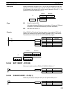
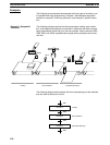
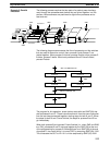
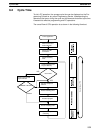
The following process requires that two parts of a product pass simultane-
ously through two processes each before they are joined together in a fifth
process. Various sensors are positioned to signal when processes are to
start and end.
Process C
SW1
SW2
Process A
SW3
SW4
Process D
Process B
Process E
SW6
SW5 SW7
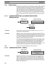
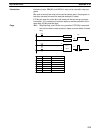
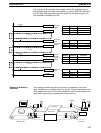
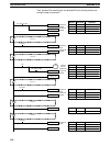
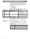
The following diagram demonstrates the flow of processing and the switches
that are used for execution control. Here, process A and process C are
started together. When process A finishes, process B starts; when process C
finishes, process D starts. When both processes B and D have finished,
process E starts.
Process A
Process E
End
Process C
SW7
Process B Process D
SW3
SW4
SW 1 and SW2 both ON
SW5 and SW6 both ON
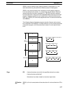
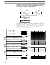
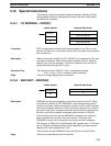
The program for this operation, shown below, starts with two SNXT(09) that
start processes A and C. These instructions branch from the same instruction
line and are always executed together, starting steps for both A and C. When
the steps for both A and C have finished, the steps for process B and D be-
gin immediately.
When both process B and process D have finished (i.e., when SW5 and SW6
turn ON), processes B and D are reset together by the SNXT(09) at the end
of the programming for process B. Although there is no SNXT(09) at the end
of process D, the control bit for it is turned OFF by executing SNXT(09) 1002.
This is because the OUT to IR 1101 is in the step reset by SNXT(09) 1002.
Example 3: Parallel
Execution
Step Instructions Section 5-18