


101
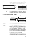
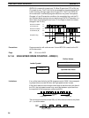
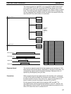
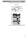
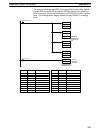
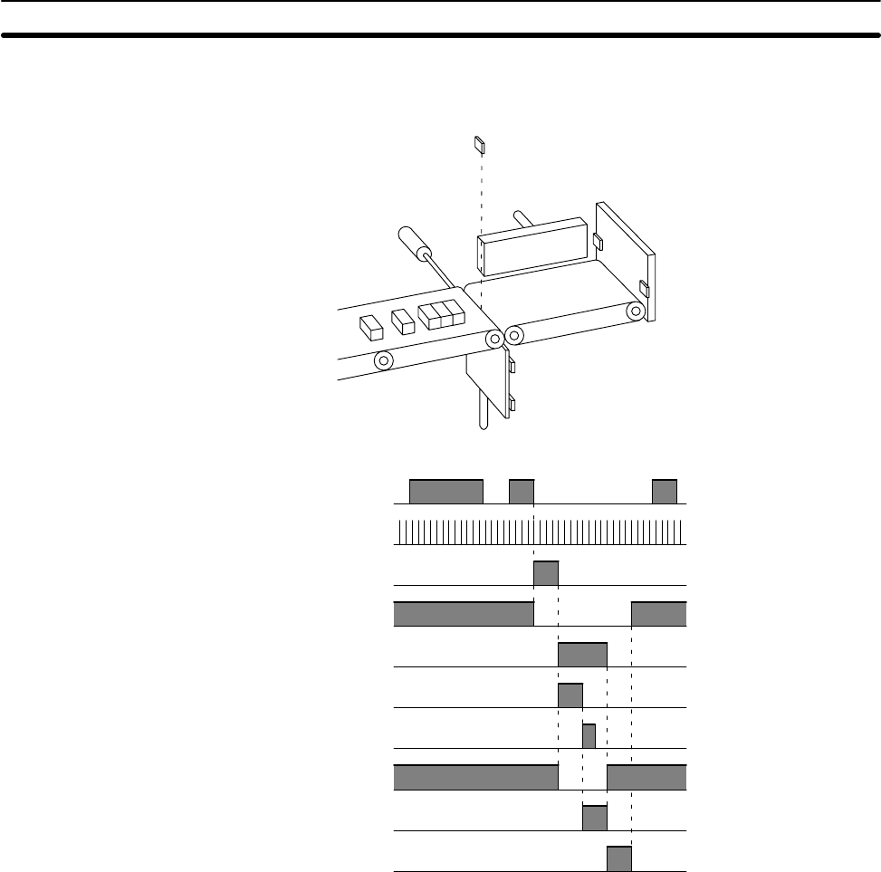
The following diagram shows the packaging system and the corresponding
timing chart.
Pusher
Packages
Rotary encoder E6A
(0000)
Reflective photoelectric
switch PH1 (0002)
Motor 2 (M2)
Rear limit switch for
pusher LS1 (0003)
Fixed stopper
Front limit switch for
pusher LS2 (0004)
Upper limit switch for stopper LS3 (0005)
Moving stopper
Lower limit switch for stopper LS4 (0006)Motor 1 (M1)
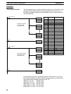
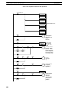
PH1
(0002)
E6A
(0000)
M1 rise
(0100)
LS4
(0006)
LS3
(0005)
M2
forward
(0102)
LS2
(0004)
LS1
(0003)
M2
backward
(0103)
M1 fall
(0101)
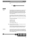
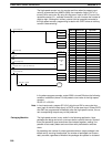
In this example, “x” is the number of pulses per package. To detect four pack-
ages therefore, 4x must be set as the preset value of the high-speed counter.
Timer and Counter Instructions Section 5-11