


Appendix BProgramming Instructions and Execution Times
177
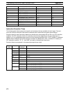
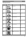
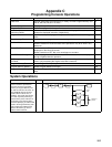
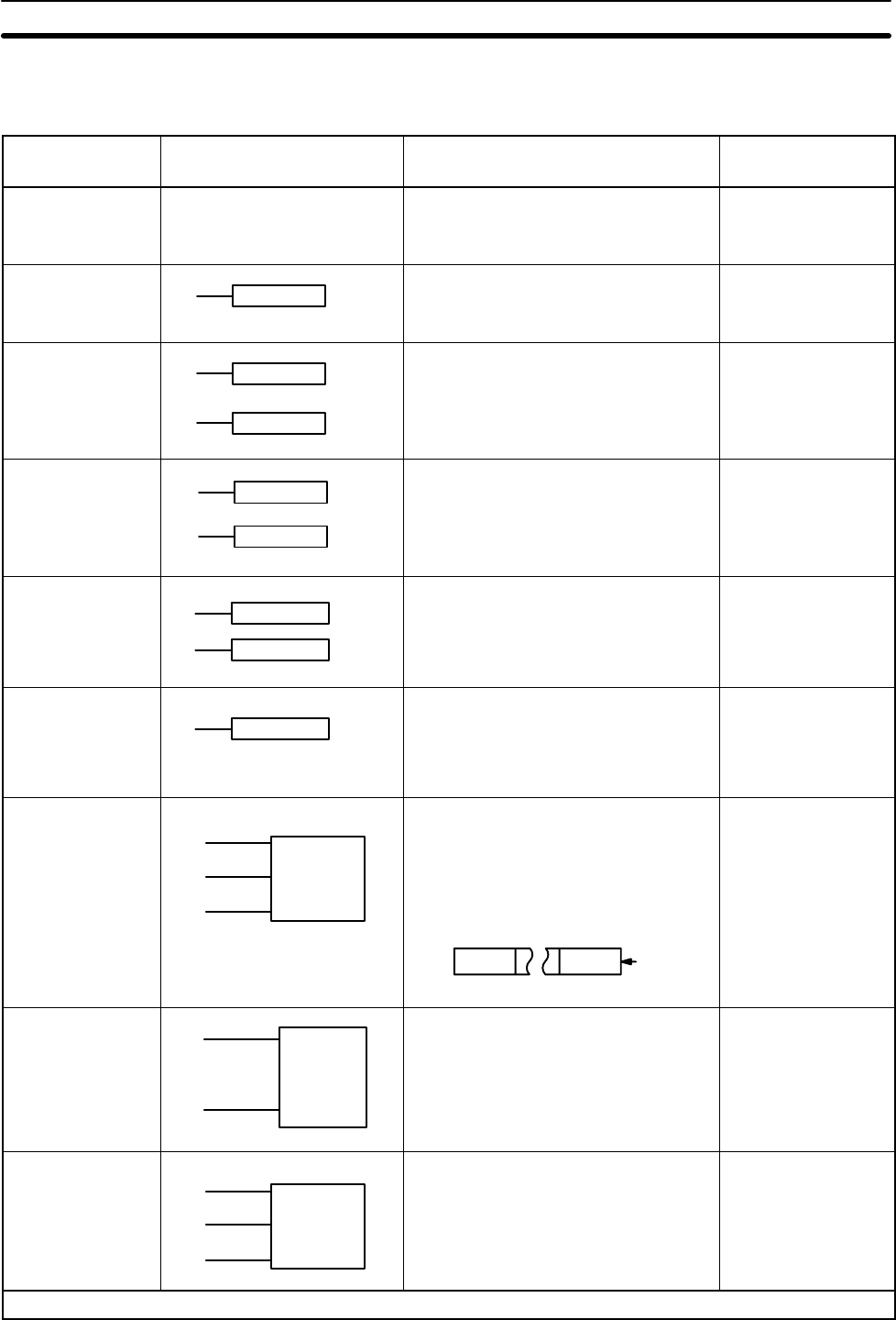
Special Instructions
Name
Mnemonic
Symbol Function Operands
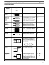
NO OPERATION
NOP (00)
None
Nothing is executed and next instruc-
tion is moved to.
None
END
END(01)
END(01)
Required at the end of the program. None
INTERLOCK
IL(02)
INTERLOCK
CLEAR
ILC(03)
IL(02)
ILC(03)
If interlock condition is OFF, all outputs
are turned OFF and all timer PVs reset
between this IL(02) and the next
ILC(03). Other instructions are treated
as NOP; counter PV are maintained.
None
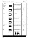
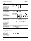
JUMP
JMP(04)
JUMP END
JME(05)
JMP(04)
JME(05)
Cause all instructions between
JMP(04) and the corresponding
JME(05) to be ignored. Corresponding
JME is next one in program; only 8
JMP-JME pairs allowed per program.
None
STEP DEFINE
STEP(08)
STEP(08) N
STEP(08)
Is used in the definition of program
sections. STEP N marks the beginning
of the section identified by N. STEP
without an operand indicates the end
of a series of program sections.
N:
HR
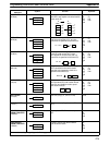
STEP START
SNXT(09)
SNXT(09) N
SNXT resets the timers and clears the
data areas used in the previous pro-
gram section. SNTX must also be
present at the end of a series of pro-
gram sections.
N:
HR
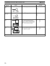
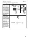
SHIFT REGISTER
SFT(10)
I
P
R
SFT(10)
St
E
Creates a bit shift register from the
starting word (St) through the ending
word (E). I: input bit; P: shift pulse; R:
reset input. St must be less than or
equal to E and Bg and E must be in the
same data area.
E
St
15 1500
IN
00
St/E:
IR
HR
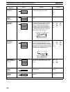
KEEP
KEEP(11)
S
R
KEEP(11)
B
Defines a bit (B) as a latch controlled
by set (S) and reset (R) inputs.
B:
IR
HR
REVERSIBLE
COUNTER
CNTR (12)
II
DI
R
N
SV
CNTR
Increases or decreases PV by one
whenever the increment input (II) or
decrement input (DI) signal goes from
OFF to ON. SV: 0 to 9999; R: reset in-
put. Must not access the same TC bit
as another timer/counter. The TC bit is
input as a constant.
N:
TC
SV:
IR
HR
#
Refer to table at beginning of Appendix B for page references.