


26
4-1 Introduction
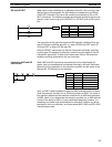
This section explains how to convert ladder diagrams to mnemonic code and
input them into the PC. It then describes the basic steps and concepts in-
volved in programming and introduces the instructions used to build the basic
structure of the ladder diagram and control its execution. The entire set of
instructions used in programming is described in
Section 5 Instruction Set
.
There are several basic steps involved in writing a program.
1, 2, 3...
1. Obtain a list of all I/O devices and the I/O points that have been as-
signed to them and prepare a table that shows the I/O bit allocated to
each I/O device.
2. If the PC has any Units, i.e. Analog Timer Units, Host Link Units , and
I/O Link Units that are allocated words in data areas other than the IR
area or are allocated IR words in which the function of each bit is speci-
fied by the Unit, prepare similar tables to show what words are used for
which Units and what function is served by each bit within the words.
3. Determine what words are available for work bits and prepare a table in
which you can allocate these as you use them.
4. Also prepare tables of TC numbers and jump numbers so that you can
allocate these as you use them. Remember, the function of a TC num-
ber can be defined only once within the program; jump numbers 01
through 08 can be used only once each. (TC numbers are described in
5-11 Timer and Counter Instructions
; jump numbers are described later
in this section.)
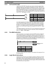
5. Draw the ladder diagram.
6. Input the program into the CPU. When using the Programming Console,
this will involve converting the program to mnemonic form.
7. Check the program for syntax errors and correct these.
8. Execute the program to check for execution errors and correct these.
9. After the entire Control System has been installed and is ready for use,
execute the program and fine tune it if required.
The basics of writing the ladder diagram and inputting it into memory are de-
scribed in the rest of this section. Debugging and monitoring operation of the
program are described in
Section 7 Program Debugging and Execution
.
Sec-
tion 8 Troubleshooting
also provides information required for debugging.
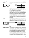
This section provides the procedures for inputting and debugging a program
and monitoring and controlling the PC through a Programming Console. The
Programming Console is the most commonly used Programming Device for
the K-type PCs. It is compact and available both in handheld models or
CPU-mounted models. Refer to
Appendix A Standard Models
for model num-
bers and other details.
If you are using a GPC, FIT, or a computer running LSS, refer to the
Opera-
tion Manual
for corresponding procedures on these.
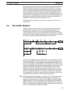
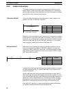
4-2 Instruction Terminology
There are basically two types of instructions used in ladder diagram program-
ming: instructions that correspond to conditions on the ladder diagram and
are used in instruction form only when converting a program to mnemonic
code and instructions that are used on the right side of the ladder diagram
and are executed according to the conditions on the instruction lines leading
to them.
Instruction Terminology Section 4-2