


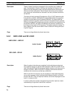
74
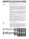
These six basic instructions correspond to the conditions on a ladder dia-
gram. As described in
Section 4 Writing and Inputting the Program
, the
status of the bits assigned to each instruction determines the execution con-
ditions for all other instructions. Each of these instructions can be used as
many times and a bit address can be used in as many of these instructions
as required.
The status of the bit operand (B) assigned to LD or LD NOT determines the
first execution condition. AND takes the logical AND between the execution
condition and the status of its bit operand; AND NOT, the logical AND be-
tween the execution condition and the inverse of the status of its bit operand.
OR takes the logical OR between the execution condition and the status of its
bit operand; OR NOT, the logical OR between the execution condition and
the inverse of the status of its bit operand. The ladder symbol for loading TR
bits is different from that shown above. Refer to
Section 4 Writing and Input-
ting the Program
.
There are no flags affected by these instructions.
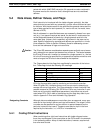
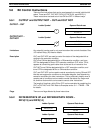
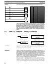
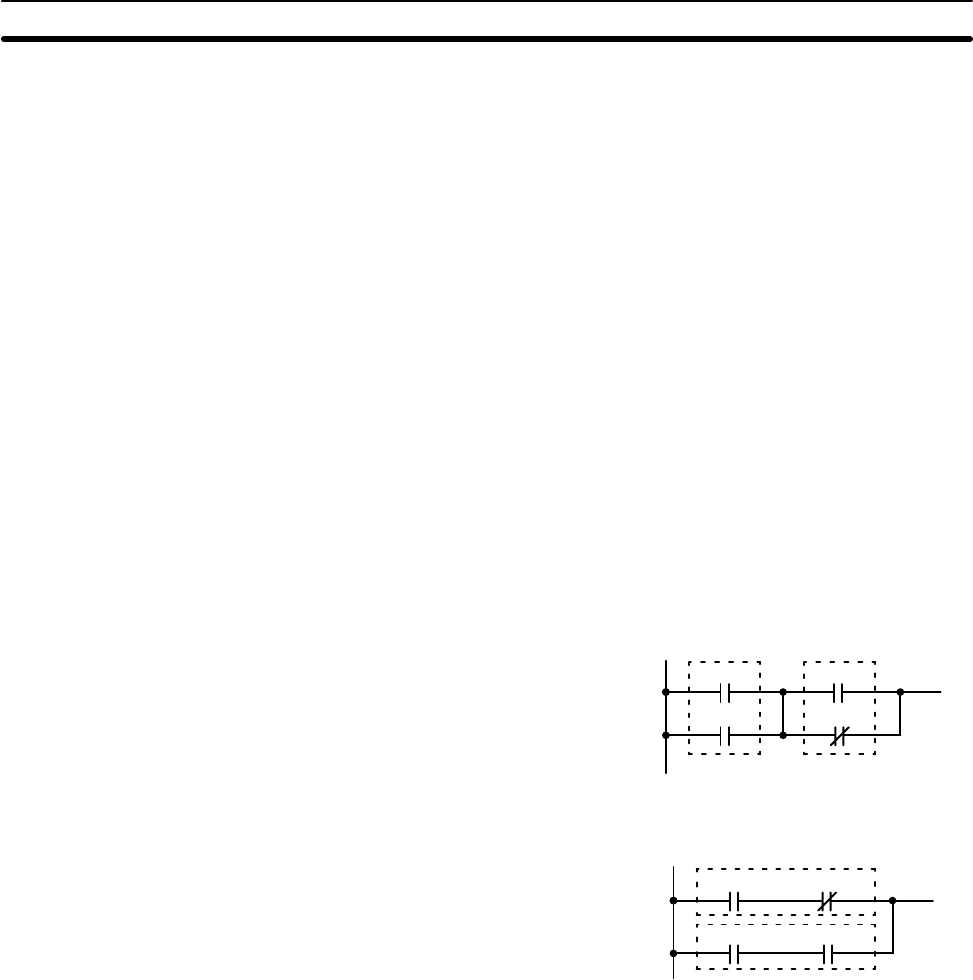
5-5-2 AND LOAD and OR LOAD
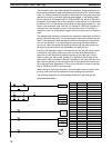
Ladder Symbol
AND LOAD – AND LD
0002
0003
0000
0001
Ladder Symbol
OR LOAD – OR LD
0000 0001
0002 0003
When the above instructions are combined into blocks that cannot be logi-
cally combined using only OR and AND operations, AND LD and OR LD are
used. Whereas AND and OR operations logically combine a bit status and an
execution condition, AND LD and OR LD logically combine two execution
conditions, the current one and the last unused one.
AND LD and OR LD instruction are not necessary to draw ladder diagrams,
nor are they necessary when inputting ladder diagrams directly, as is possi-
ble from the GPC. They are required, however, to convert the program to and
input it in mnemonic form.
In order to reduce the number of programming instruction required, a basic
understanding of logic block instructions is required.
There are no flags affected by these instructions.
Description
Flags
Description
Flags
Ladder Diagram Instructions Section 5-5