


38
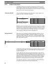
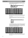
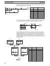
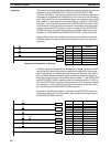
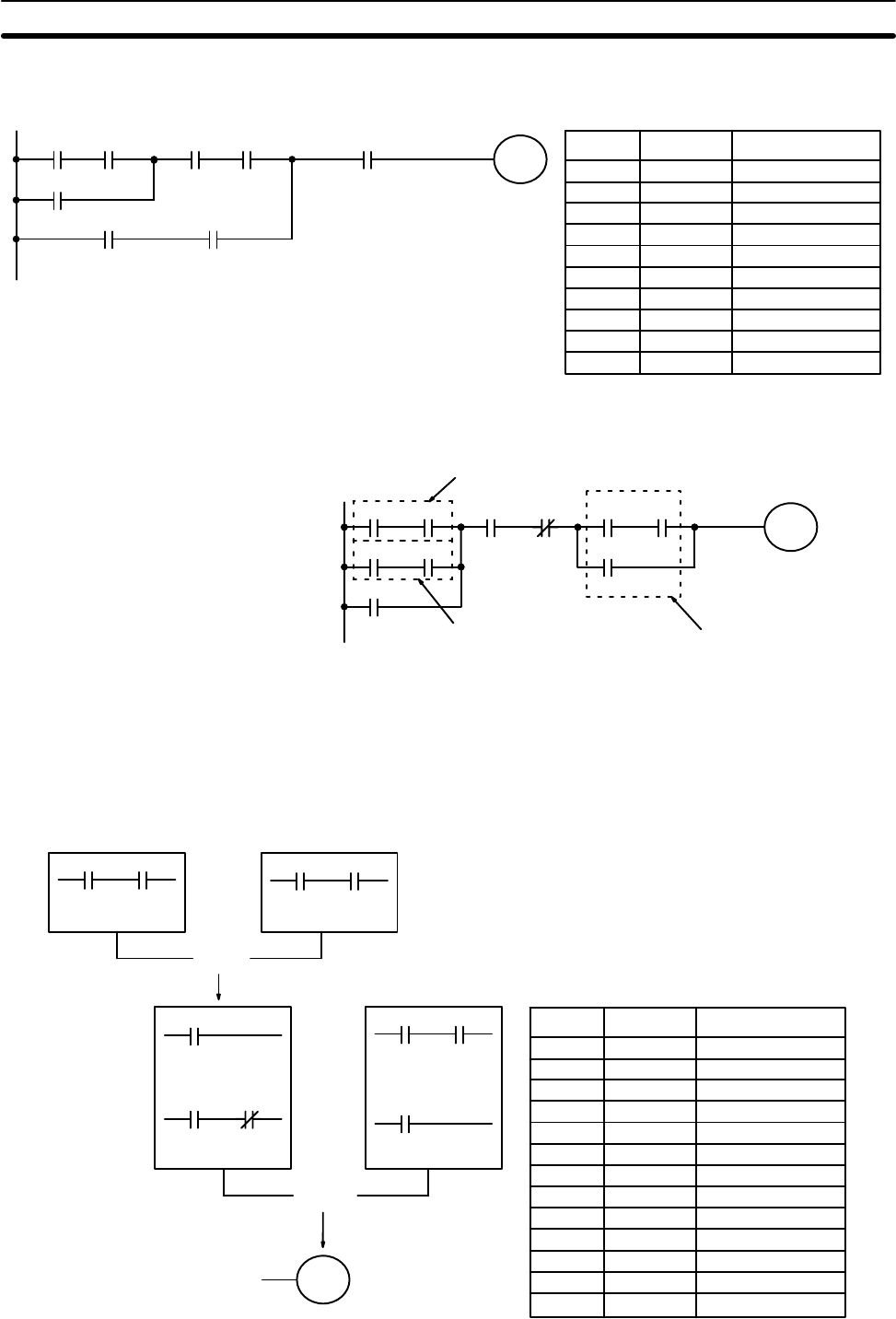
Again, this diagram can be redrawn as follows to simplify program structure
and coding and to save memory space.
0006 0007
0105
0005
0001 0002
0003 0004 0000
Address Instruction Operands
0000 LD 0006
0001 AND 0007
0002 OR 0005
0003 AND 0003
0004 AND 0004
0005 LD 0001
0006 AND 0002
0007 OR LD ---
0008 AND 0000
0009 OUT 0105
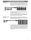
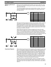
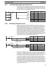
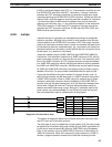
Our last example may at first appear very complicated but can be coded us-
ing only two logic block instructions. The diagram appears as follows:
0000 0001
0105
0002 0003
0100 0101
0004 0005
0500
0006
Block c
Block b
Block a
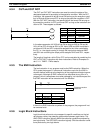
The first logic block instruction is used to combine the execution conditions
resulting from blocks a and b, and the second one is used to combine the
execution condition of block c with the execution condition resulting from the
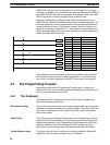
normally closed condition assigned 0003. The rest of the diagram can be
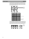
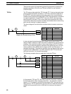
coded with ladder instructions. The logical flow for this and the resulting code
are shown below.
0000 0001
0105
0002 0003
0100 0101
0004 0005
0500
0006
Block c
Block bBlock a
OR LD
LD 0000
AND 0001
OR 0500
AND 0002
AND NOT 0003
LD 0100
AND 0101
OR 0006
LD 0004
AND 0005
AND LD
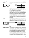
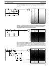
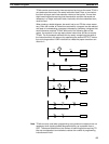
Address Instruction Operands
0000 LD 0000
0001 AND 0001
0002 LD 0100
0003 AND 0101
0004 OR LD ---
0005 OR 0500
0006 AND 0002
0007 AND NOT 0003
0008 LD 0004
0009 AND 0005
0010 OR 0006
0011 AND LD ---
0012 OUT 0105
The Ladder Diagram Section 4-3