


107
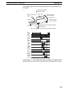
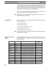
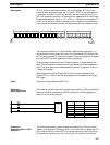
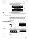
SFT(10) shifts an execution condition into a shift register. SFT(10) is con-
trolled by three execution conditions, I, P, and R. If SFT(10) is executed and
1) execution condition P is ON and was OFF the last execution and 2) R is
OFF, then execution condition I is shifted into the rightmost bit of a shift regis-
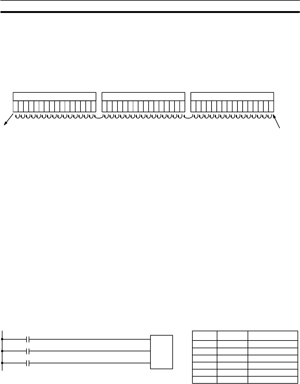
ter defined between St and E, i.e., if I is ON, a 1 is shifted into the register; if I
is OFF, a 0 is shifted in. When I is shifted into the register, all bits previously
in the register are shifted to the left and the leftmost bit of the register is lost.
Execution
condition I
Lost
data
E St + 1, St + 2, ... St
The execution condition on P functions like a differentiated instruction, i.e., I
will be shifted into the register only when P is ON and was OFF the last time
SFT(10) was executed. If execution condition P has not changed or has gone
from ON to OFF, the shift register will remain unaffected.
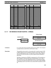
St designates the rightmost word of the shift register; E designates the left-
most. The shift register includes both of these words and all words between
them. The same word may be designated for St and E to create a 16-bit (i.e.,
1-word) shift register.
When execution condition R goes ON, all bits in the shift register will be
turned OFF (i.e., set to 0) and the shift register will not operate until R goes
OFF again.
There are no flags affected by SFT(10).
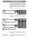
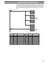
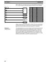
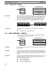
The following example uses the 1-second clock pulse bit (1902) to so that the
execution condition produced by 0005 is shifted into a 3-word register be-
tween 10 and 12 every second.
I
P
SFT(10)
10
12
R
0005
1902
0006
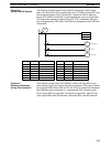
Address Instruction Operands
0000 LD 0005
0001 LD 1902
0002 LD 0006
0003 SFT(10)
10
12
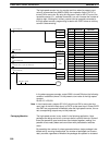
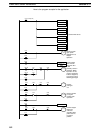
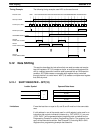
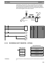
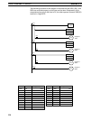
The following program is used to control the status of the 17th bit of a shift
register running from IR 00 through IR 01 (i.e. bit 00 of IR 01). When the 17th
bit is to be set, 0204 is turned ON. This causes the jump for JMP(04) 00 not
to be made for that one cycle and IR 0100 (the 17th bit) will be turned ON.
Description
Flags
Example 1:
Basic Application
Example 2:
Controlling Bits in Shift
Registers
Data Shifting Section 5-12