


4 - Principles of Operation
46
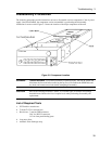
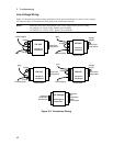
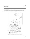
As shown in Figure 6-2, the ac input rectifier and filter converts ac input to a dc level. The output regulator
regulates this dc level at the output of the power supply. The output regulator stage consists of two parallel
NPN series regulators mounted on a heatsink and connected between the +Rail and the +Output. The
conduction of these series regulators is increased or decreased by the Control signal from the CV/CC
control circuits in order to regulate the output voltage (in CV mode), or output current (in CC mode).
An NPN downprogramming transistor is connected between the +Output and the -Rail. The conduction of
the downprogramming transistor is controlled by the DP_Control signal from the CV/CC control circuits.
Whenever the output voltage is greater than the programmed voltage setting, the downprogramming
transistor conducts and shunts current away from the load until the output voltage equals the programmed
setting.
The SCR, connected across the output, will fire and short the output when an overvoltage condition is
detected. The SCR is controlled by the OV_SCR* signal from the crowbar control circuit (described in the
next section).
Two current shunt resistors (RmHi and RmLo) monitor the output current. RmHi monitors the high current
range; RmLo monitors the low current range. Shunt clamps are connected in parallel across RmLo to limit
the voltage across RmLo to about 2 volts. This corresponds to approximately 25 mA (the maximum rating
of the low current range).
The output filter capacitor provides additional filtering of the dc output.
Control Circuits
As shown in Figure 6-2, the control circuits consist of the CV/CC control, output voltage/current monitor,
bias supplies, and SCR control.
The CV/CC control circuits provide a CV control loop and a CC control loop. For any value of load
resistance, the supply must act either as a constant voltage (CV) or as a constant current (CC) supply.
Transfer between these modes is accomplished automatically by the CV/CC control circuit at a value of
load resistance equal to the ratio of the programmed voltage value to the programmed current value. A low
level CV_Detect* or CC_Detect* signal is returned to the secondary interface to indicate that the
corresponding mode is in effect.
With the CV loop in control, the output voltage is regulated by comparing the programmed voltage signal
CV_Prog (0 to -5V) with the output voltage monitor signal VMon. The VMon signal is in the 0 to +5 V
range, which corresponds to the zero to full-scale output voltage range of the supply. If the output voltage
exceeds the programmed voltage, the Control signal goes low, causing the output regulator to conduct less
and decrease the output voltage. Conversely, if the output voltage is less than the programmed voltage, the
Control signal goes high, causing the regulator to conduct more and increase the output voltage. Depending
upon the position of the Sense switch, the output voltage is either monitored at the supply's output terminals
(local), or at the load (remote), using the +S and -S terminals with remote sense leads connected to the load.
If the output voltage goes higher than the programmed value, the downprogramming stage is turned on.
With the CC loop in control, the output current is regulated by comparing the programmed current signal
CC_Prog (0 to -5V), with the output current monitor signal Imon_H. The Imon_H signal is produced by
measuring the voltage drop across current monitoring resistor and is in the 0 to +3.5 V range, which
corresponds to the zero to full-scale output current range. If the output current exceeds the programmed
value, the Control signal goes low, causing the output regulator to conduct less and thus decrease the output
current. Conversely, if the output current is less than the programmed value, the Control signal goes high,
causing the output transistors to conduct more and increase the output current. A gross current limit circuit
protects the output if the output current exceeds the maximum current rating of the unit.