Troubleshooting - 3
29
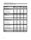
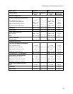
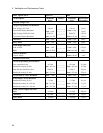
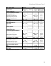
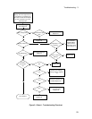
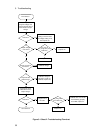
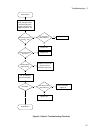
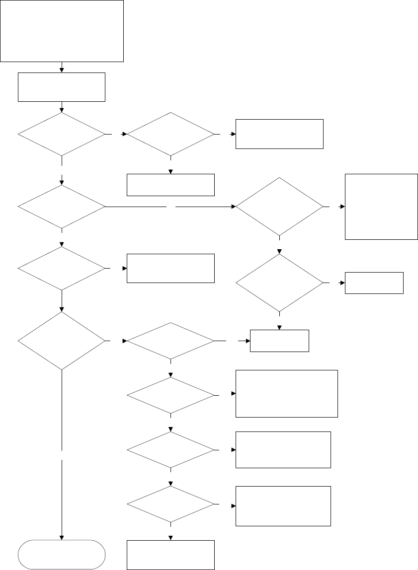
Figure 3-1 Sheet 1. Troubleshooting Flowchart
Turn on unit and observe the
display. All of the segments and
annunciators, the address and
then after self test should display
an error message or go to the
metering mode.
Display comes on?
+5V @ A2J211-1 (to
chassis)?
Replace A3
Check A1F305,
Red/White/Black
cable A1-A2 &
cable A2-A3, track
on A2 (J206-J211)
Error Message?
Yes
Go to Error Message
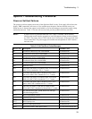
Table 3-2.
Yes
Protect
annunciator
on?
No
RI?
Yes
OV?
No
Check for OV setting <
Voltage setting, Replace
A1
Yes
OC?
No
Check that OCP is not
enabled, Replace A1
Yes
FS?
No
Check F309 (fuse near
main heat sink),
Replace A1
Yes
For OT check fan,
Replace A1
No
Go to Sheet 2
No
No
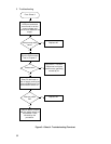
A3J111-5 low (no
pulses)?
Yes
No
Replace A2
Yes
Check Bias voltages
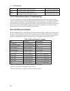
(see Table 3-3)
Bias voltages OK? Transformer Inputs
OK?
No
Yes
Check Main Fuse,
Replace T1
No
Replace A1
Yes
No
Yes


